In modern industrial screening systems, vibration is the core driving force behind material separation efficiency. When engineers or procurement managers evaluate vibrating screen solutions, one key question always arises: should you choose a vibrating screen exciter or a vibration motor?
Vibrating Screen Exciter vs Vibration Motor: Which Is Better?
This is not a simple “which is better” question. The answer depends on application scenarios, material characteristics, operational goals, and long-term cost considerations. In this article, we will break down the differences between these two vibration sources in a clear and practical way, helping you make an informed decision that aligns with real production needs.
1. Understanding the Basics
Before comparing performance, it is important to clarify how each system works.
What Is a Vibrating Screen Exciter?
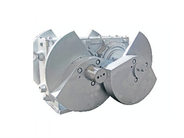
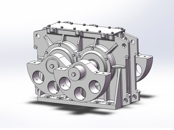
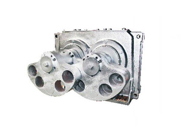
A vibrating screen exciter is a mechanical device that generates vibration through rotating shafts equipped with eccentric masses. It is typically driven by an external motor via a belt or coupling. The exciter converts rotational motion into a stable, high-intensity linear or circular vibration.
In most industrial applications, exciters are installed on large vibrating screens used in mining, aggregate processing, and heavy-duty material classification.
What Is a Vibration Motor?
A vibration motor is an integrated unit where the motor and eccentric weights are combined into a single compact device. When the motor rotates, the adjustable eccentric blocks generate centrifugal force, creating vibration directly.
Vibration motors are widely used in smaller equipment such as feeders, light-duty screens, and compact conveying systems.
2. Structural Differences and Design Logic
The fundamental difference lies in how vibration is generated and transmitted.
A vibrating screen exciter separates the power source (motor) and the vibration generator (exciter).
A vibration motor integrates both functions into one unit.
This design distinction leads to significant differences in performance, durability, and flexibility.
Exciters are engineered for high-load, continuous operation, while vibration motors are designed for simplicity and convenience.
3. Performance Comparison
3.1 Vibration Strength and Stability
A vibrating screen exciter can produce stronger and more stable vibration forces. Because it uses synchronized shafts and precise gear systems, it ensures consistent amplitude even under heavy loads.
…
For more detailed information on vibration screen exciters and vibration motors: which is better, please click to visit: https://www.hsd-industry.com/news/vibrating-screen-exciter-vs-vibration-motor/