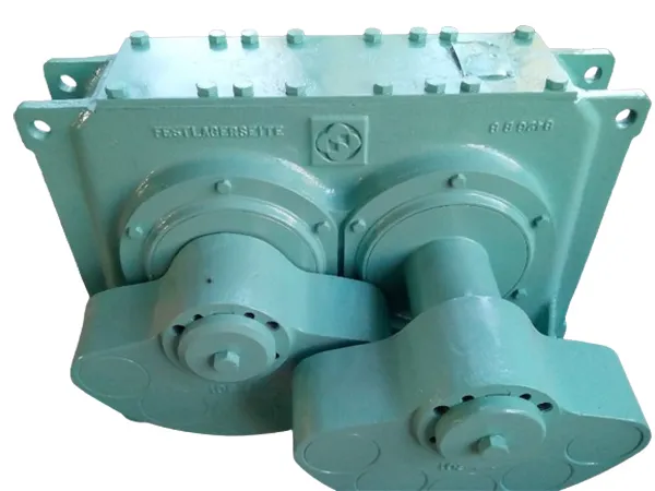
Installing a vibration motor requires careful attention to alignment, support, and mounting to ensure reliable operation and minimize wear or vibration transmission to unwanted areas.

General guide on vibration motor installation:

vibration motor

1. Prepare the Installation Surface

Ensure the surface where the motor will be mounted is clean, level, and rigid. Any unevenness or instability in the mounting surface can cause excessive vibration and reduce motor life.

Reinforce the mounting area if necessary, as a strong foundation will help absorb vibration and prevent damage to surrounding equipment.

2. Mounting the Motor

Use bolts that are strong enough for the motor’s size and vibration force. High-grade bolts are recommended to secure the motor tightly.

Place vibration-damping pads or rubber mounts between the motor and the mounting surface to help absorb vibrations and prevent them from transferring to other parts of the machine.

Tighten the bolts evenly to ensure that the motor is securely and uniformly attached. This helps to distribute the load and minimize imbalances.

3. Alignment and Positioning

Align the motor properly with the vibrating equipment to avoid misalignment, which can cause excessive wear and increase vibrations.

Position the motor according to the manufacturer’s recommendations, as improper placement can lead to uneven or excessive vibrations. For example, some setups may require placing the motor at a specific angle or orientation.

Make sure there is sufficient clearance around the motor for maintenance and to allow airflow for cooling.

vibration motor

4. Electrical Connections

Follow the manufacturer’s wiring instructions carefully to connect the motor to the power supply. Make sure to use appropriately rated cables and connectors.

Use cable clamps to secure the wiring to prevent it from being affected by vibrations, which can lead to wear or electrical issues over time.

Ground the motor properly to ensure safety and prevent electrical noise from affecting nearby equipment.

More detailed information about vibration motor installation guide can be found at:https://www.zexciter.com/en/a/news/vibration-motor-installation.html

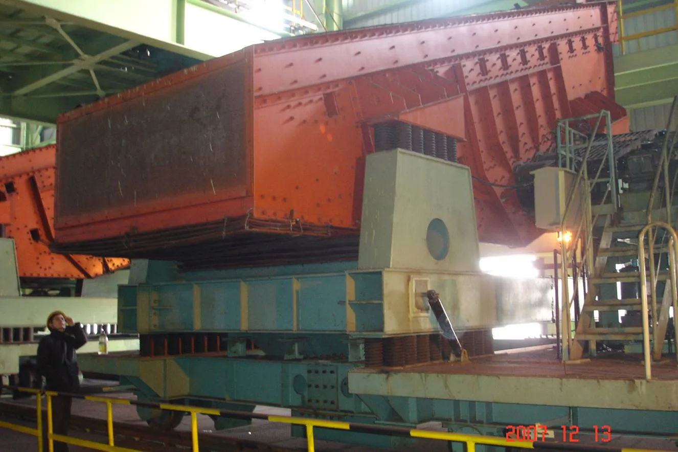
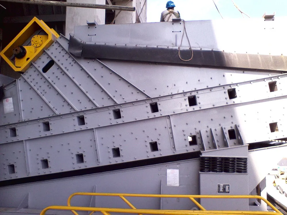
Installing bearings in a vibrating screen is a critical task that requires precision to ensure that the machine operates effectively, minimizes downtime, and maximizes bearing life. Vibrating screens operate under harsh conditions, with heavy loads and high vibration, so proper bearing installation is essential to prevent premature failure.

Vibrating screen bearing installation

vibrating screen

1. Prepare for Installation

Gather Tools and Materials: Make sure you have the necessary tools and equipment, including the correct bearings, tools for mounting (e.g., bearing pullers, wrenches, hammers), grease or lubricant, cleaning materials, and any special tools for your screen design.

Ensure Proper Conditions: Perform the installation in a clean, dry environment to avoid contamination of the bearings. If necessary, use a workbench with sufficient space to handle the components.

2. Inspect the Bearings

Check for Damage: Before installation, inspect the bearings for any signs of damage (such as cracks or dents) or contamination. Ensure the bearings are the correct size and type for your vibrating screen.

Clean Bearings: If the bearings are new, ensure they are free of dirt or debris. Wipe the bearings with a clean cloth if needed. If you’re reusing old bearings, thoroughly clean them before installation.

3. Prepare the Housing and Shaft

Inspect the Shaft and Housing: Ensure that the shaft and housing where the bearings will be installed are in good condition. Look for any wear, damage, or signs of corrosion that could affect bearing performance.

Clean the Shaft and Housing: Clean both the shaft and bearing housing with a lint-free cloth to remove any dirt, dust, or oil. If necessary, lightly polish the surfaces with a fine abrasive cloth.

Check for Tolerances: Verify that the shaft and housing have the correct dimensions to match the bearing’s internal and external diameters. The fit should not be too tight or too loose.

4. Install the Bearings

Apply Grease or Lubrication: If the bearings are grease-lubricated, apply a thin layer of grease to the inner race and the shaft. Use only the recommended type and amount of lubricant. If the bearing is sealed, it may not require lubrication before installation.

Use Bearing Installation Tools: Use proper tools to install the bearings. It is crucial not to damage the bearing by applying force directly to the rolling elements (balls or rollers). Use bearing fitters or sleeves to apply pressure to the outer race of the bearing only.

Install the Bearing on the Shaft: Gently slide the bearing onto the shaft, ensuring it moves smoothly without excessive force. Do not hammer or force the bearing onto the shaft. If the bearing is tight, use a press to push it into place evenly.

Install the Bearing in the Housing: Similarly, install the other bearing into the bearing housing. Ensure that the bearing is properly seated and aligned with the housing.

vibrating screen

5. Align the Bearings

Check Alignment: Proper alignment of the bearings is crucial to prevent premature wear or failure. Use alignment tools or a straight edge to check that both the shaft and housing are properly aligned.

Ensure Proper Radial and Axial Clearance: Depending on the bearing type, ensure that the radial and axial clearance meet the specifications for the vibrating screen application.

For more detailed information on vibrating screen bearing installation, please click here: https://www.zexciter.com/en/a/news/vibrating-screen-bearing-installation.html

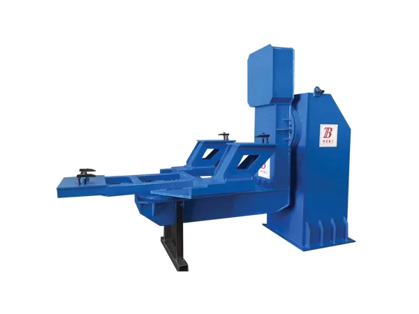
Welding column boom is an important equipment used for welding work. To ensure its normal operation and safe use, it is important to perform regular maintenance.

Contents of welding column boom maintenance

1. Electrical system maintenance

Check whether the electrical components such as the power line, switch, button and controller of the welding column boom are intact, and perform necessary maintenance and replacement. Check whether the joints of the welding cable and connector are loose or damaged, and perform necessary cleaning and tightening. Check whether the power supply and grounding of the welding machine are normal to ensure the safety and reliability of the electrical system.

2. Mechanical structure maintenance

Check whether the frame, support and connecting parts of the welding column boom are firm. If they are loose or worn, they should be repaired or replaced in time. Check the transmission system of the welding operation machine, including transmission belts, chains, gears, etc., to ensure its normal operation and transmission efficiency.

Check the guide system of the welding column boom, including guide rails, guide columns, etc., to ensure the stability and accuracy of the welding head.

3. Lubrication system inspection

Check the lubrication system of the welding column boom, including the oil pump, oil pipe, oil nozzle, etc., to ensure the smooth supply and circulation of the lubricating oil. Replace the lubricating oil, and clean or replace the oil filter to ensure the normal operation of the lubrication system. According to the use of the welding operator, determine the lubrication cycle and lubrication parts, and perform lubrication maintenance regularly.

4. Welding power supply inspection

Check the welding power supply part of the welding column boom, including the transformer, rectifier, capacitor, etc., to ensure its normal operation and safety. Check the cooling system of the welding power supply, including the fan, heat sink, etc., to ensure that the heat dissipation effect of the welding power supply is good.

Clean the inside and outside of the welding power supply to ensure good heat dissipation and prevent dust and dirt from affecting the welding power supply.

5. Safety device inspection

Check the safety devices of the welding column boom, such as the emergency stop button, leakage protector, etc., to ensure their normal operation and safety.

Test the leakage current and insulation resistance of the welding column boom to ensure the safe use of the welding column boom.

Matters needing attention in the overhaul of the welding column boom

1. Safe operation

When carrying out overhaul, be sure to follow the safe operating procedures and never ignore safety issues. If necessary, disconnect the power supply and put up warning signs to prevent accidental start-up and injury.

For more detailed information on the maintenance and precautions of welding column boom, please click to visit: https://www.bota-weld.com/en/a/news/welding-column-boom-maintenance.html

With the continuous development of modern industry, welding technology, as an important means of connecting metal structures, is increasingly used in the manufacturing industry. However, the quality control of welding column boom is particularly important to ensure the stability of the welding process and the quality of the welded joints, so as to ensure high energy efficiency and safety during the welding process.

Analysis of key points of quality control of welding column boom

welding column boom

1. Operator training and certification

In the quality control of welding column boom, the training and certification of operators are very important. Only welders who have undergone professional training and qualified certification can master the use skills of welding column boom and effectively deal with various complex situations. The training content includes welding principles, equipment operation, safety knowledge, etc., to ensure that the operators have comprehensive technical literacy.

2. Welding process specifications and parameter control

In the process of use, formulating scientific and reasonable welding process specifications is an important part of ensuring welding quality. The reasonable setting of parameters such as welding current, voltage, welding speed, and the formulation of process requirements such as preheating and post-weld treatment have a direct impact on the strength and stability of the welded joint. Accurately controlling these parameters can improve welding quality and reduce the occurrence of welding defects.

3. Welding material quality control

The quality control of welding column boom also requires strict quality inspection and control of welding materials. Including the inspection of welding materials such as welding wire, flux, and welding rod to ensure that they meet relevant standards and specifications. Qualified welding materials can not only improve the firmness of the welded joint, but also reduce the occurrence of defects such as pores and slag inclusions during the welding process.

welding column boom

4. Equipment maintenance and calibration

Equipment maintenance and calibration are key steps to ensure its normal operation and welding quality. Regularly maintain the welding machine, check the wear and damage of components such as welding power supply, electrode head, transmission system, etc., replace and repair them in time to ensure that the equipment is in good working condition. At the same time, regular calibration is performed to ensure the accuracy and stability of welding parameters.

For more detailed information on the key points of quality control of welding column boom, please click to visit: https://www.bota-weld.com/en/a/news/welding-column-boom-quality-control.html

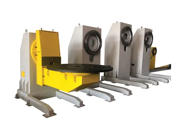
Welding rotators, also known as turning rolls, are devices that rotate cylindrical or round objects like pipes, tanks, and vessels, enabling easier welding and better control over the welding process. There are several types of welding rotators, each designed for specific applications and workpiece sizes.

Welding rotator types

Welding rotator

1. Conventional Welding Rotators

Fixed Rotators: The idler and drive units are fixed in position. They are suitable for workpieces with consistent diameters and are typically used when there is no need for adjustment.

Adjustable Rotators: The spacing between the rollers can be adjusted to accommodate different workpiece diameters, allowing greater flexibility. These rotators often feature screw or bolt mechanisms for manual adjustment.

2. Self-Aligning Welding Rotators

These rotators automatically adjust the roller angle to accommodate workpieces of varying diameters, eliminating the need for manual adjustment.

They are ideal for applications with different pipe or vessel sizes and are commonly used in industries where quick setup and high production efficiency are required.

3. Turning Rolls with Variable Speed Control

These rotators have adjustable speed controls, allowing the operator to change the rotational speed to match the welding requirements.

Variable speed rotators provide precise control, which is essential for high-quality welding, especially in applications requiring consistent weld bead quality.

Welding rotator

4. Fit-Up Rotators

Fit-up rotators are specially designed to align and fit pipes or vessels before welding, helping to reduce the need for manual alignment.

They typically feature independent control of each roller, which allows for fine adjustment of the workpiece alignment before welding begins.

More detailed information about welding rotator types can be found at: https://www.bota-weld.com/en/a/news/welding-rotator-types.html

Installing a welding column and boom requires careful planning and adherence to safety guidelines due to the heavy and complex equipment involved. Here’s a step-by-step guide to help you set it up:

Welding column boom installation

welding column and boom

1. Prepare the Installation Site

Choose a location: Select a flat, stable surface in a well-ventilated area with enough clearance for the boom’s full range of movement.

Check load-bearing requirements: Ensure the floor can support the weight of the column, boom, and any additional attachments or equipment.

2. Gather Equipment and Tools

Lifting equipment: You’ll need a crane or forklift to position heavy components.

Anchor bolts and baseplate: These secure the column to the floor.

Safety gear: Hard hats, gloves, steel-toed boots, and eye protection.

Hand tools: Wrenches, sockets, level, measuring tape, and a torque wrench.

3. Position and Anchor the Column

Mark the foundation: Measure and mark where the anchor bolts will go, making sure it aligns with the column baseplate.

Drill anchor holes: Use a heavy-duty drill to make holes for the anchor bolts.

Lift and align the column: Use a crane or forklift to position the column over the anchor bolts.

Secure the column: Fasten the baseplate to the floor using anchor bolts, tightening them to the recommended torque.

4. Attach the Boom to the Column

Position the boom: Carefully align the boom with the mounting bracket on the column.

Secure with bolts: Attach the boom to the column with heavy-duty bolts, and tighten to the manufacturer’s specifications.

Check for alignment: Use a level to ensure the boom is properly aligned with the column.

welding column and boom

5. Install Electrical and Pneumatic Connections

Connect wiring: Ensure the column-boom assembly has the necessary electrical wiring for controls, motorized movements, and sensors.

Run air and gas lines: If your welding application requires gas or air, connect these lines securely.

6. Perform a Test Run

Inspect movement: Test the boom’s range of motion to ensure smooth, unrestricted movement.

For more detailed information on welding column boom installation, please click here: https://www.bota-weld.com/en/a/news/welding-column-boom-installation.html

In today’s increasingly tight resources, improving the material utilization rate of industrial equipment has become an important means for enterprises to reduce costs and enhance competitiveness. As a kind of equipment widely used in metallurgy, building materials, chemical industry and other industries, the material utilization rate of the briquetting machine is directly related to the production efficiency and economic benefits of the enterprise. This article will explore how to effectively improve the material utilization rate of the ball press through a series of measures, in order to provide a reference for related industries.

Material utilization rate of the briquetting machine

briquetting machine

1. Accurately control the moisture content of the material

The moisture content of the material is a key factor affecting the molding effect of the briquetting machine. If the moisture content is too low, the adhesion between the materials is insufficient, resulting in the fragile pellets after molding; if the moisture content is too high, the pellets will be too soft and lack strength. Therefore, it is very important to accurately control the moisture content of the material. This can be achieved by adjusting the amount of water added during the mixing process or pre-drying the material before pressing.

2. Reduce impurities in the material

Impurities not only affect the quality of the pellets, but may also damage the ball press. By removing impurities in the material by pre-screening or using methods such as magnetic separation, the purity of the material can be improved, thereby improving the material utilization rate of the ball press.

3. Reasonable use of additives

The use of additives can improve the molding performance of materials, but they need to be reasonably selected according to the characteristics of the materials and production requirements. The right amount of additives can improve the strength and molding rate of the pellets, but excessive use will increase costs and even affect the quality of the pellets.

4. Optimize the particle size of the material

The particle size of the material has a direct impact on the molding effect of the briquetting machine. Too large or too small particles will affect the molding effect of the material. Generally, the particle size of the material should be controlled between 80 and 200 meshes to ensure uniform gaps between material particles and improve molding quality.

5. Improve the purity of the material

The higher the purity of the material, the better its molding effect. High-purity materials can reduce the impact of impurities on the molding effect, improve the strength and durability of the pellets, and thus improve the material utilization rate of the ball press.

More detailed information about briquetting machine material utilization can be found at: https://www.zymining.com/en/a/news/briquetting-machine-material-utilization-rate.html

In the field of industrial production, especially for those industries that need to convert powdered materials into pellets with specific shapes and strengths, high-pressure briquetting machines play a vital role. As a key component in the briquetting machine, the design and performance of the pre-pressing screw directly affect the pretreatment effect of the material and the quality of the final pellets. This article will discuss in detail the design points of the pre-pressing screw of the high-pressure briquetting machine, aiming to provide reference and guidance for the technological progress and equipment upgrades of related industries.

Design of pre-pressing screw of high-pressure briquetting machine

high-pressure briquetting machine

1. Driving mode of pre-pressing screw

The driving mode of pre-pressing screw is the core of its design. Usually, the pre-pressing screw is driven by an AC variable frequency reduction motor, which can provide constant torque to ensure that the material is subjected to uniform and stable force during the pre-pressing process. Another advantage of the variable frequency motor is that the speed can be adjusted according to the material characteristics and production requirements, thereby achieving accurate control of the pre-pressure.

2. Material and wear resistance of pre-pressing screw

The material selection of the pre-pressing screw is crucial because it directly affects the service life and maintenance cost of the equipment. Generally speaking, the pre-pressing screw shaft is made of high-strength alloy steel to ensure its stability and durability under high pressure. The spiral blades are coated with wear-resistant materials, such as carbide or ceramic materials, to reduce wear and extend the service life of the equipment.

3. Pitch design of pre-pressing spiral

The pitch design has an important influence on the working efficiency of the pre-pressing spiral and the fluidity of the material. Reasonable pitch design can ensure the continuous flow of materials during the pre-pressing process to avoid blockage and accumulation. The cylindrical variable pitch design is a common choice for pre-pressing spirals, which can provide gradually increasing pressure during the pre-pressing process to adapt to the characteristics of different materials.

high-pressure briquetting machine

4. Sealing performance of pre-pressing spiral

The sealing performance between the pre-pressing spiral and the roller is crucial to maintaining the stability of the internal environment of the briquetting machine. Good sealing can prevent material leakage and the entry of external impurities, thereby protecting the roller and extending the service life of the equipment. The stepped labyrinth seal is a commonly used sealing method, which realizes the effective sealing of the gap between the pre-pressing spiral and the roller through the cooperation of multiple sealing rings.

For more detailed information on the design of the high pressure press preloading spiral, please click here: https://www.zymining.com/en/a/news/key-points-for-designing-the-pre-pressing-screw-of-high-pressure-briquetting-machine.html

The drive system of a high-pressure grinding roller (HPGR) is a crucial component that powers the rollers to perform efficient grinding under high pressure, a process commonly used in mining, cement, and aggregate industries. This system is responsible for providing the necessary torque and controlling the speed and load to optimize the grinding process.

The main aspects of an HPGR drive system

High-pressure grinding roller

1. Drive Types

Single Motor Drive: A single motor powers both rollers, typically through a gearbox and coupling arrangement. This setup can be simpler but may require a more complex transmission system to ensure synchronized roller rotation.

Dual Motor Drive: Each roller has its own motor, providing more control and flexibility. Dual motor drives are preferred in large-capacity or high-torque applications because they ensure that both rollers can operate independently while maintaining synchronized movement.

Hydraulic Drive: In some designs, hydraulic systems are used to drive the rollers. Hydraulic drives provide high torque and smooth control, which can be advantageous for handling varying material loads and ensuring even pressure distribution.

2. Control System

Variable Frequency Drive (VFD): VFDs are used to control the speed of the motors, allowing operators to adjust the roller speed based on the feed material characteristics and required grinding pressure. This flexibility is critical for optimizing efficiency and reducing wear on the rollers.

Load-Sensing System: A load-sensing mechanism monitors the pressure exerted on the rollers. The system adjusts the torque and speed accordingly to maintain consistent grinding pressure, which helps to optimize throughput and protect the rollers from overloads.

PLC and Automation: Many HPGR systems use programmable logic controllers (PLCs) with automation capabilities to monitor and adjust parameters in real-time. This helps to maintain a stable grinding process, reduce energy consumption, and improve the lifespan of the equipment.

3. Torque Control and Distribution

HPGR drive systems are designed to generate high torque to withstand the high-pressure grinding process. Torque control ensures even distribution of pressure across the roller width, preventing uneven wear on the rollers.

Dual motor drives often use torque distribution controls to synchronize the rotation of both rollers, balancing the load and optimizing material throughput.

High-pressure grinding roller

4. Gearbox and Couplings

Gearboxes in HPGR systems are robust and designed to handle high loads. Planetary gearboxes or helical gear systems are commonly used due to their high efficiency and torque-handling capabilities.

For more detailed information about the transmission system of high pressure grinding roll, please click to visit: https://www.zymining.com/en/a/news/high-pressure-roller-grinding-machine-drive-system.html

Safe operating procedures for compound crushers are essential for minimizing hazards and ensuring efficient, trouble-free operation. Compound crushers combine impact and compression crushing for breaking down materials, so here’s a guide on safe practices:

Safety operating procedures for compound crusher

compound crushers

1. Pre-Operational Checks

Inspect for damage: Before starting, check for any visible damage or wear on the crusher, including the feed hopper, crushing chamber, belts, and motor.

Ensure proper lubrication: Check lubrication points and oil levels to ensure all moving parts have adequate lubrication to avoid overheating and wear.

Clear the area: Ensure no unauthorized personnel are near the crusher during operation, as moving parts can be hazardous.

2. Starting the Crusher

Start in sequence: Begin by starting the ancillary equipment (conveyors, screens) before powering the crusher.

Observe for abnormalities: Listen for unusual noises or vibrations during startup. If you notice anything abnormal, stop the machine immediately for inspection.

Monitor feed size: Only feed materials within the crusher’s designed size limit to avoid blockages and damage.

3. Feeding Material

Uniform feed rate: Feed materials steadily and uniformly to prevent blockages and overloading, which can cause strain on the crusher components.

Avoid foreign objects: Ensure no metal or uncrushable objects enter the crusher, as these can cause severe damage to the machinery.

Avoid overfeeding: Overloading the crusher can lead to jams, overheating, or mechanical failure, so maintain a balanced feed.

4. During Operation

Regular monitoring: Check for abnormal sounds, vibrations, or excessive temperature changes in bearings and motors.

Adjust settings as needed: Some compound crushers allow adjustment of crushing speed or gap; make sure these settings are within the manufacturer’s recommendations.

For more detailed information on the safe operation procedures of compound crusher, please click to visit: https://www.zymining.com/en/a/news/safety-operating-procedures-for-compound-crusher.html