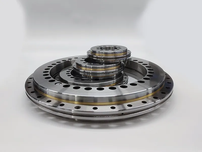
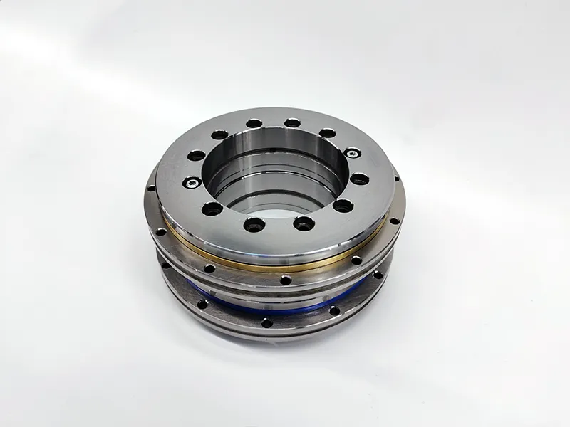
Angular contact ball bearings are a type of rolling-element bearing designed to handle both axial and radial loads by supporting the shaft in both axial and radial directions. Here’s a guide covering sizes, types, applications, and general pricing information.

Angular contact ball bearings guide

H70C-ACP4 Ultra High Speed Series

Sizes

Angular contact ball bearings come in various sizes, and their dimensions are typically specified by the bore diameter (d), outside diameter (D), and width (B). Common size ranges include:

  • Bore Diameter (d): From a few millimeters to several hundred millimeters.
  • Outside Diameter (D): Typically ranges from tens of millimeters to several meters.
  • Width (B): Varies depending on the specific design and application requirements.

Sizes are usually standardized, and specific dimensions can be found in catalogs provided by manufacturers.

Types

Single-Row Angular Contact Ball Bearings:

  • Suitable for carrying axial loads in one direction and limited radial loads.
  • Can be paired to accommodate axial loads in both directions.

Double-Row Angular Contact Ball Bearings:

  • Consist of two rows of balls separated by a central rib.
  • Capable of handling higher radial and axial loads.

More detailed information about the Angular Contact Ball Bearing Guidelines can be found here: https://www.lkwebearing.com/news-center/angular-contact-ball-bearings-guide.html

Currently, the commonly used matched bearings for machine tool spindles are angular contact ball bearings. Usually, complete sets of matched bearings are used. In some cases, non-complete sets of angular contact ball bearings may be used for universal matching. However, universal matching faces inconsistent accuracy. , inconsistent ruler time, inconsistent angle, etc., what are the universal matching requirements for angular contact ball bearings? And how to improve the matching accuracy? The following editor has compiled relevant content for you, hoping to be helpful to you.

What are the universal matching requirements for angular contact ball bearings?

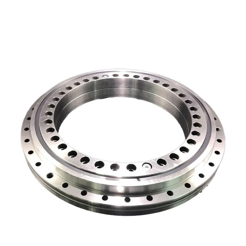
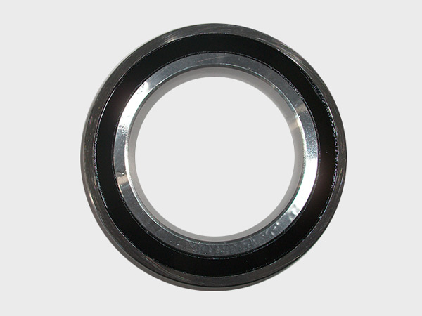
PX Sealed 4 Point Contact Ball Bearing Series

When pairing angular contact ball bearings, in addition to relying on high-precision equipment during the production process to directly ensure the mutual differences in the inner and outer diameter groove dimensions, groove curvature, and groove position, the contact angle, the mutual difference in the inner and outer diameter dimensions, and the protrusion amount must also be ensured. Wait for the request.

1. Contact angle

The contact angle of universal matched angular contact ball bearings directly affects the stress state of the bearing under working conditions. The contact angle difference between two matched sets of bearings should be as small as possible. Generally, the contact angle difference between precision and ultra-precision matched bearings is About 1°. When selecting, the contact angle is controlled by controlling the radial clearance according to the relationship between the radial clearance and the contact angle.

cosβ= 1-Y/2 (Re+ Ri-2Rw)

In the formula:

β – contact angle

Y – radial clearance

Re – outer ring groove curvature radius

Ri – inner ring groove curvature radius

Rw – steel ball radius

As can be seen from the above formula, the difference in curvature radius of the inner and outer ring grooves can be effectively controlled during processing. Using the same set of steel balls for assembly can reduce the impact on the contact angle. Controlling the contact angle by fine-tuning the radial clearance can improve the angular contact Universal matching accuracy of ball bearings.

More detailed information on the general fit requirements for angular contact ball bearings can be found here: https://www.lkwebearing.com/news-center/angular-contact-ball-bearing-matching-requirements.html

welding positioner is a specialized piece of equipment used in welding applications to position a workpiece in the optimal orientation for welding. It helps welders to achieve better precision, accessibility, and efficiency in the welding process. The positioner allows for the rotation or tilting of the workpiece, making it easier for the welder to reach all necessary angles without having to reposition themselves.The installation of a welding positioner involves several key steps to ensure its proper setup and safe operation.

Welding positioner installation process

welding positioner

1. Site Preparation

Choose a location for the welding positioner that provides sufficient space for safe operation and easy access. Ensure that the floor is level and can support the weight of the positioner.

2. Unpacking and Inspection

Carefully unpack the welding positioner and inspect it for any shipping damage. Check for all the components listed in the user manual.

3. Positioner Placement

Place the welding positioner in the desired location. If it is a large or heavy unit, use appropriate lifting equipment to move it into place.

4. Leveling

Use a level to ensure that the welding positioner is perfectly level. This is critical for accurate and stable positioning during welding.

welding positioner

5. Securing the Positioner

Once leveled, secure the welding positioner to the floor using appropriate anchors or fasteners. This step is essential for stability and safety during operation.

6. Power Connection

Connect the welding positioner to the power source according to the manufacturer’s specifications. Ensure that the power supply meets the equipment requirements.

For more detailed information about the welding positioner installation process, please click here: https://www.bota-weld.com/en/a/news/welding-positioner-installation-process.html

ball press machine, also known as a briquette press or pellet press, is a device that compacts powder or granular material into larger, more manageable forms. These machines are commonly used in various industries for shaping materials into uniform, dense balls or briquettes, typically for ease of storage, transportation, or further processing.

Components of a Ball Press Machine

ball press machine

Hopper:

The hopper is where the raw material, such as powder or fine particles, is loaded into the machine.

Auger or Screw Conveyor:

An auger or screw conveyor transports the raw material from the hopper to the compression chamber.

Compression Chamber:

The compression chamber is where the actual compaction process takes place. The raw material is compressed into a specific shape, often a ball or cylindrical form, using mechanical pressure.

Rollers or Dies:

Rollers or dies inside the compression chamber help shape and compress the material into the desired form.

Hydraulic or Mechanical System:

The machine is equipped with a hydraulic or mechanical system that provides the force necessary for the compaction process.

Control Panel:

The control panel allows operators to adjust and control parameters such as pressure, temperature, and the speed of the machine.

Operation of a Ball Press Machine

ball press machine

Loading:

The raw material is loaded into the hopper.

Transportation:

The auger or screw conveyor moves the material from the hopper to the compression chamber.

For more detailed information about what is a briquetting machine, please click here: https://www.zymining.com/en/a/news/what-is-a-ball-press-machine.html

A harmonic reducer, also known as a strain wave gear or harmonic drive, is a type of precision gear mechanism used for speed reduction in various applications, particularly in robotics, aerospace, and industrial automation. The harmonic reducer bearing is known for its compact size, high torque density, and accuracy. It operates on the principle of elastic deformation to achieve gear reduction.Here’s an introduction to the main components and working principles of a harmonic reducer.

Components

harmonic reducer bearing

Wave Generator (Input Shaft): The wave generator is the input component that generates a wave-like motion, typically through an eccentric cam. This wave motion is transmitted to the flexspline.

Flexspline (Flexible Circular Spline): The flexspline is a thin, flexible, and toothed circular disc that deforms under the influence of the wave generator’s motion. It is the output element of the system.

Circular Spline (Fixed Outer Gear): The circular spline is a rigid, toothed ring that meshes with the flexspline. It is fixed in place and provides the necessary reaction to the flexspline’s deformation.

Working Principle

harmonic reducer bearing

Elastic Deformation: The key principle of a harmonic reducer is the elastic deformation of the flexspline. As the wave generator rotates, it creates a wave motion in the flexspline, causing it to deform. The deformation allows the teeth on the flexspline to engage with the teeth on the circular spline.

Zero-Backlash: One of the advantages of harmonic reducers is their minimal backlash. Backlash is the play or clearance between gear teeth. In a harmonic drive, the meshing of teeth is achieved through elastic deformation, reducing or eliminating backlash.

High Torque Density: Harmonic reducers are known for their high torque density, meaning they can provide significant torque output in a compact and lightweight design. This makes them suitable for applications where space and weight are critical factors.

For more detailed information on the working principle of harmonic reduction bearings, please click here: https://www.boyingbearing.com/en/a/news/working-principle-of-harmonic-reducer-bearings.html

Mobile healthcare shelving plays a crucial role in medical institutions by contributing to the efficiency, organization, and accessibility of medical supplies, equipment, and records.

The roles of mobile healthcare shelving in medical institutions

Mobile healthcare shelving

Space Optimization

Mobile shelving systems are designed to maximize the use of available space. In healthcare settings where space is often limited, these shelving units can be compacted or expanded as needed, allowing for better space utilization.

Organization and Storage

Mobile shelving provides a systematic and organized way to store medical supplies, documents, and equipment. It helps in categorizing items, making it easier for healthcare professionals to locate and access what they need promptly.

Flexibility and Adaptability

The mobility of these shelving units allows for easy reconfiguration of storage space. This adaptability is especially valuable in healthcare environments where storage needs may change frequently due to evolving equipment requirements or changes in the volume of supplies.

Infection Control

Mobile healthcare shelving systems are often designed with materials and features that facilitate easy cleaning and maintenance. This is crucial in medical institutions where maintaining a clean and sterile environment is essential for infection control.

Mobile healthcare shelving

Secure Storage of Sensitive Items

Mobile shelving units can include locking mechanisms to secure sensitive medical supplies, pharmaceuticals, or confidential patient records. This helps in maintaining the security and privacy of critical items and information.

Efficient Retrieval of Supplies

With mobile shelving, healthcare professionals can access supplies quickly, reducing the time spent searching for items. This efficiency is particularly important in emergency situations where timely access to medical equipment and supplies can be critical.’

For more detailed information about the role of mobile medical shelves in medical institutions, please click here: https://www.etegreen.com/en/a/news/the-role-of-mobile-healthcare-shelving-in-medical-institutions.html

mobile cabinet is a type of storage unit designed for mobility, allowing users to move it easily from one location to another. These cabinets are equipped with wheels or casters, making them versatile and convenient for various applications across different environments. Here’s an introduction to mobile cabinets, highlighting their features, types, and common uses:

Features of Mobile Cabinets

Mobile Cabinets

Wheels or Casters: The defining feature of mobile cabinets is the presence of wheels or casters, which enable easy movement. These can be swivel or fixed, depending on the design and intended use.

Locking Mechanism: Many mobile cabinets come with a locking mechanism to secure the contents during transport or when stationary. This is particularly important for applications where the cabinet may hold valuable or sensitive items.

Materials: Mobile cabinets can be constructed from a variety of materials, including metal, wood, plastic, or a combination of these materials. The choice of material often depends on the intended use and durability requirements.

Handles or Grips: To facilitate movement, mobile cabinets typically have handles or grips. These may be integrated into the design of the cabinet or added as attachments.

Shelving or Drawers: Depending on the purpose, mobile cabinets may feature shelves, drawers, or a combination of both. This allows for organized storage of items, making them easily accessible.

Types of Mobile Cabinets

Mobile Cabinets

Tool Cabinets: Used in workshops, garages, or industrial settings, these cabinets are designed to store and organize tools. They often have drawers, shelves, and compartments for different tool types.

For more detailed information about the introduction of mobile cabinets, please click to visit: https://www.rff-global.com/a/news/mobile-cabinets-introduction.html

turntable bearing, also known as a lazy Susan bearing, is a specialized type of rotational bearing that allows for smooth and controlled rotation of a platform or turntable. These bearings are commonly used in various applications where the ability to rotate objects is required, such as in lazy Susans, swiveling chairs, rotating displays, industrial machinery, and other systems. The design of turntable bearings allows for low-friction, precise rotation, and they come in different configurations to meet specific needs.

The size of a turntable bearing, often referred to as a lazy Susan bearing, is typically specified by its diameter. Turntable bearings come in various sizes to accommodate different applications. The size is usually given in inches or millimeters, representing the diameter of the circular raceway where the turntable rotates.

turntable bearing

The collection of turntable bearing sizes

4 Inches (100 mm): Common for small to medium-sized applications, such as rotating displays, cabinets, or light-duty turntables.

6 Inches (150 mm): Slightly larger than the 4-inch size, suitable for applications requiring a bit more load capacity.

8 Inches (200 mm): Widely used for various purposes, including rotating tabletops, kitchen cabinets, and other medium-duty applications.

12 Inches (300 mm): Larger size suitable for heavier applications, such as industrial turntables, display platforms, or rotating stages.

For more detailed information about the dimensions of turntable bearings, please click here: https://www.prsbearings.com/a/news/turntable-bearing-size.html

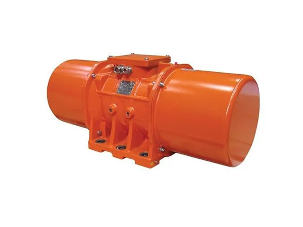
A vibrating screen vibrator, also known simply as a vibrator or vibrating motor, is an essential component of a vibrating screen. Vibrating screens are used in various industries for separating and sizing aggregates, minerals, and other granular materials based on particle size. The vibrating screen vibrator is responsible for generating the vibratory motion that facilitates the screening process.

Introduction to vibrating screen vibrator

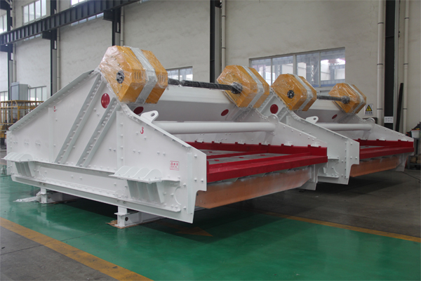
Linear vibrating screen

1. Types of Vibrators

Electric Vibrators: These are the most common types of vibrating screen vibrators. They are powered by electric motors and are versatile, providing adjustable vibration intensity.

Pneumatic Vibrators: Powered by compressed air, pneumatic vibrators are suitable for applications where electric power may not be readily available or in hazardous environments.

Hydraulic Vibrators: Driven by hydraulic power, these vibrators are often used in heavy-duty applications and can provide high force.

2. Key Components

Motor: The core component of the vibrator is an electric, pneumatic, or hydraulic motor that generates the rotational force required for vibration.

Eccentric Weights: In many vibrating screen vibrators, eccentric weights are attached to the motor’s shaft. The rotation of these weights creates a centrifugal force, resulting in vibratory motion.

Housing: The motor and eccentric weights are housed in a protective casing designed to withstand the forces generated during operation.

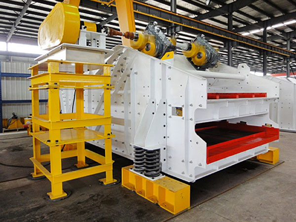
High Frequency Dehydration Vibrating Screen

3. Adjustability

Vibrators are often designed to be adjustable to control the amplitude (intensity) of the vibration. This adjustability allows operators to optimize the screening process for different materials and operating conditions.

4. Mounting

Vibrators are typically mounted to the vibrating screen structure. The mounting method may vary depending on the design of the screen, but common methods include side-mounted vibrators or vibrators mounted at the screen’s center.

5. Maintenance

Regular maintenance is essential to ensure the efficient operation of the vibrating screen vibrator. This may include lubrication of bearings, inspection of eccentric weights, and checking for any signs of wear or damage.

For more detailed information about the vibrating screen vibrator sister, please click to visit: https://www.hsd-industry.com/news/introduction-to-vibrating-screen-vibrator/

Replacing a tractor clutch is a mechanical task that requires precision and attention to detail. The specific steps can vary depending on the make and model of the tractor, so it’s essential to consult the tractor’s service manual for accurate instructions. Here is a general guide that outlines the typical steps involved in replacing a tractor clutch:

Tools and Equipment Needed

Service manual for the tractor

Wrenches

Socket set

Screwdrivers

Pry bar

Jack and jack stands

Clutch alignment tool

Torque wrench

Replacement clutch kit

Tractor Clutch Replacement Steps

Consult the Service Manual

  • Review the tractor’s service manual for specific instructions and specifications related to the clutch replacement. The manual will provide information on the type of clutch used, torque specifications, and any special instructions.

Safety Precautions

  • Ensure the tractor is on a level surface and engage the parking brake.
  • Disconnect the battery to prevent any electrical issues during the replacement.

Remove External Components

  • Remove any covers, guards, or other components that may be obstructing access to the clutch assembly.

Drain Fluids (if required)

  • If the tractor has a hydraulic clutch, you may need to drain the hydraulic fluid according to the manufacturer’s guidelines.

For more detailed information on the tractor clutch replacement process, click here: https://www.syclutch.com/news/tractor-clutch-replacement-process.html