tractor clutch kit typically refers to a set of components that includes the clutch disc, pressure plate, release bearing, and sometimes an alignment tool. These components are essential parts of a tractor’s clutch system, allowing the tractor to engage and disengage the engine from the transmission. When the clutch pedal is depressed, it disengages the clutch, allowing the tractor to change gears or come to a stop without turning off the engine.

The components in a tractor clutch kit
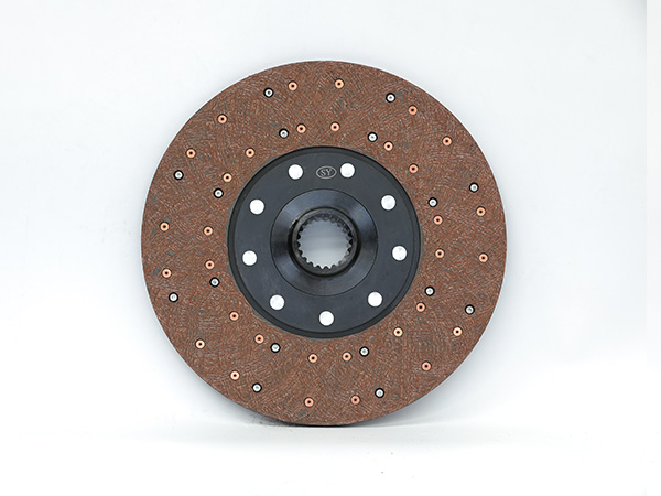
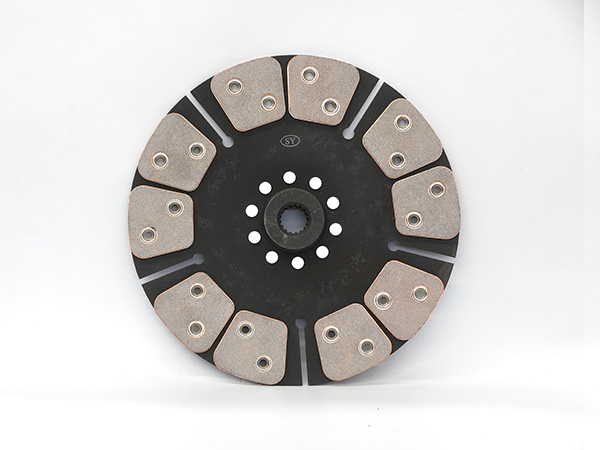
13-Inch-16-Spline-with-Spring

1. Clutch Disc

The clutch disc is the main component that engages with the flywheel and the pressure plate. It contains friction material on both sides and is squeezed between the pressure plate and the flywheel to transmit power from the engine to the transmission.
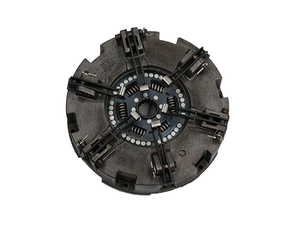
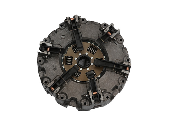
2. Pressure Plate:

The pressure plate is a heavy metal plate that, when engaged, presses the clutch disc against the flywheel. This pressure allows power to be transferred from the engine to the transmission. When you release the clutch pedal, the pressure plate disengages, allowing the engine and transmission to spin independently.

3. Release Bearing (Throw-Out Bearing):

The release bearing is a bearing encased in a collar. When you press the clutch pedal, the release bearing moves toward the pressure plate, releasing the pressure on the clutch disc and disengaging the clutch. It’s a critical component for smooth clutch operation.

4. Alignment Tool:

Some clutch kits come with an alignment tool. This tool helps in aligning the clutch disc properly during installation, ensuring that the transmission input shaft fits smoothly through the center hole of the clutch disc.

Important Considerations

Compatibility: Ensure that the clutch kit you choose is compatible with the specific make and model of your tractor. Tractor models can vary widely, so it’s important to get the right parts for your tractor.

For more detailed information about the components of the tractor clutch kit, please click here: https://www.syclutch.com/news/tractor-clutch-kit-components.html

Replacing bearings in a harmonic reducer is a task that requires precision and attention to detail. Harmonic reducers, also known as strain wave gears or wave generators, are critical components in robotics, automation systems, and other high-precision applications. If you are facing the need to replace the bearings in a harmonic reducer, follow these steps to ensure a successful replacement process.

Harmonic reducer bearing replacement

Harmonic reducer bearing

1. Safety First

  • Ensure the equipment is powered off and completely shut down.
  • Wear appropriate safety gear, including gloves and safety glasses, to protect yourself during the replacement process.

2. Documentation

  • Consult the manufacturer’s technical documentation for your specific harmonic reducer model. This documentation will provide crucial information about disassembly, bearing types, and torque specifications.

3. Disassembly

  • Carefully disassemble the harmonic reducer according to the manufacturer’s guidelines. This may involve removing screws, bolts, or other fasteners that hold the housing together.
  • Keep track of the disassembled parts and their arrangement. Take pictures if necessary to aid in reassembly.

4. Bearing Removal

  • Use appropriate tools and techniques to remove the old bearings from the harmonic reducer. This may involve using bearing pullers or presses to safely extract the bearings without damaging the housing or other components.
  • Inspect the bearing seats and housing for any signs of wear, deformation, or damage. Address any issues before installing new bearings.

5. Selecting Replacement Bearings

  • Choose high-quality replacement bearings that match the specifications provided by the manufacturer. Consider factors such as bearing type, size, load capacity, and tolerance levels.
  • Ensure the replacement bearings are compatible with the operating conditions of the harmonic reducer.Harmonic reducer bearing

6. Installation

  • Clean the bearing seats and shafts thoroughly before installing the new bearings. Remove any dirt, debris, or remnants of the old bearings.
  • Carefully press the new bearings into place using a hydraulic press or other suitable methods. Ensure the bearings are seated securely and evenly.
  • Follow the manufacturer’s recommendations for bearing preloading and torque specifications during installation. Over-tightening or under-tightening can lead to premature failure.

7. Reassembly

  • Reassemble the harmonic reducer components in the reverse order of disassembly. Use the pictures and notes taken during disassembly to guide you in the reassembly process.
  • Tighten fasteners to the specified torque values, ensuring that all parts are securely attached.

For more detailed information on the installation of harmonic reducer bearings, please click here: https://www.prsbearings.com/a/news/harmonic-reducer-bearing-replacement.html

Thin-walled bearings, also known as thin-section bearings or slim bearings, are designed with a smaller cross-section than standard bearings. These bearings are used in applications where space is limited and a compact design is essential. Thin-walled bearings are available in various sizes, primarily categorized based on their bore diameter, outer diameter, and width. The sizes of thin-walled bearings can vary widely based on the specific requirements of the application and the manufacturer’s offerings.

Common dimension ranges for thin-walled bearings

Thin-walled bearings

Bore Diameter: Thin-walled bearings can have bore diameters ranging from a few millimeters to several hundred millimeters. Small-sized bearings are suitable for delicate instruments and devices, while larger ones are used in industrial machinery.

Outer Diameter: The outer diameter of thin-walled bearings can also vary significantly, ranging from a few centimeters to well over a meter. Larger outer diameters are often used in heavy machinery and specialized equipment.

Width: The width of thin-walled bearings typically corresponds to the size of the cross-section. Thin-section bearings are characterized by their slim profiles, making them ideal for applications with limited space.

Thin-walled bearings

Series and Types: Thin-walled bearings come in various series and types, including radial contact, angular contact, and four-point contact designs. Each type is suitable for different load and speed requirements.

Material: Thin-walled bearings are commonly made from chrome steel, stainless steel, or other specialized materials, depending on factors such as corrosion resistance and load capacity requirements.

For more detailed information about the dimensions of thin-walled bearings, please click here: https://www.prsbearings.com/a/news/thin-walled-bearings-dimensions.html

In the realm of particle separation and material processing, vibrating screens stand as indispensable workhorses. These versatile machines are pivotal in industries ranging from mining and construction to agriculture and recycling. In this technical exploration, we delve into the intricate world of vibrating screens, unraveling their structure, functionalities, and innovative advancements that drive efficiency in various applications.

I. Anatomy of a Vibrating Screen

A vibrating screen consists of several key components, each playing a vital role in the process of material separation:

Linear vibrating screen

  • Screen Surface: The screen surface is the primary component where material separation occurs. It can be made of woven wire mesh, perforated metal, or other materials designed to suit the specific application.
  • Vibrating Motor: The vibrating motor imparts vibrations to the screen surface, facilitating the movement of particles across the screen and through openings.
  • Screen Box: The screen surface and vibrating motor are housed within the screen box, which provides support and containment for the vibrating assembly.
  • Deck(s): Vibrating screens can have multiple decks or layers, allowing for the simultaneous separation of different particle sizes. Each deck comprises its screen surface and corresponding vibrating motor.
  • Springs and Suspensions: Springs and suspensions support the screen box, allowing it to vibrate freely while absorbing excess energy. Proper suspension ensures smooth operation and longevity of the vibrating screen.

II. Functionality and Principles of Operation

Vibrating screens operate based on the principle of stratification and screening efficiency. When material is fed onto the screen surface, smaller particles pass through the openings, while larger particles are conveyed along the screen surface until they find an opening that allows them to pass through.

High Frequency Dehydration Vibrating Screen

  • Screening Efficiency: Screening efficiency is influenced by factors such as screen inclination, amplitude of vibrations, and the shape and size of openings in the screen surface. Optimal design ensures the efficient separation of particles.
  • Stratification: Vibrating screens promote stratification, where smaller particles settle to the bottom of the material layer and larger particles rise to the top. This stratification allows for precise separation of particles based on size and shape.

For more detailed information about the vibrating screen, please click here: https://www.hsd-industry.com/news/introduction-to-vibrating-screen/

Vibrating screens are widely used in various industries for separating and screening different materials. They consist of a screen body, vibration mechanism, drive motor, and various components designed to facilitate the screening process.

The key parts of a vibrating screen

Single layer horizontal sieve

1. Screen Body

The screen body is the main structure of the vibrating screen. It is typically made of welded or bolted steel parts and serves as a supporting base for the screen mesh.

2. Screen Mesh

The screen mesh is the actual screen surface where the material is separated. It can be made of various materials such as metal, woven wire, polyurethane, rubber, or perforated plates. The choice of material and the configuration of the mesh depend on the specific application and the type of material being screened.

3. Vibration Mechanism

The vibration mechanism is responsible for generating the vibratory motion of the screen. It usually consists of eccentric shafts, counterweights, and other mechanical parts. The vibration motion agitates the material, allowing smaller particles to fall through the openings in the screen mesh.

4. Drive Motor

The drive motor provides the power to operate the vibrating screen. It is connected to the vibration mechanism and generates the necessary force to create the vibratory motion.

Linear Vibrating Screen

5. Springs and Suspensions

Springs or other suspension systems are used to support and isolate the vibrating screen from the surrounding structure. Proper suspension is essential to ensure smooth and efficient operation, as it absorbs excessive vibrations and allows the screen to move freely.

6. Supporting Structure

The supporting structure includes beams, columns, and other components that provide stability and support for the vibrating screen. It ensures that the screen operates smoothly without excessive vibration or wobbling.

For more detailed information about the components of the vibrating screen, please click here: https://www.hsd-industry.com/news/vibrating-screen-composition/

A drawer sample cabinet is a specialized storage unit used in various industries, including laboratories, manufacturing, research, and quality control, to store and organize samples, specimens, tools, or other small items. These cabinets are typically equipped with multiple drawers, each of which can be labeled, segmented, or configured to accommodate specific types of samples or materials. Drawer sample cabinets are designed to keep items secure, well-organized, and easily accessible.

Features of Drawer Sample Cabinets

drawer sample cabinet

Multiple Drawers: Drawer sample cabinets consist of multiple drawers, usually arranged in a vertical or horizontal configuration, providing ample storage space for samples.

Labeling and Segmentation: Drawers often come with labels or customizable inserts, allowing users to categorize and identify the contents of each drawer easily.

Variety of Sizes: These cabinets come in various sizes to accommodate different sample sizes and storage requirements.

Security: Many drawer sample cabinets are equipped with locks or security features to ensure the safety and confidentiality of stored items.

Durability: They are typically made from sturdy materials such as steel or other metals, ensuring durability and longevity.

drawer sample cabinet

Ventilation: Some cabinets are designed with ventilation features to maintain proper airflow, which is essential for certain types of samples or materials.

Organization: Drawers can be designed with dividers, foam inserts, or other organizational features to keep samples neatly arranged and prevent mixing or damage.

For more detailed information about what a drawer sample cabinet is, click to visit: https://www.rff-global.com/a/news/what-is-drawer-sample-cabinet.html

Assembling tapered roller bearings involves a careful process to ensure they are installed correctly and function optimally. Here’s a step-by-step guide to help you assemble tapered roller bearings:

Tools and Materials Needed

Tapered roller bearings

Bearing grease

Clean rags

Bearing installation tools (e.g., bearing installer tool)

Torque wrench

Lubrication equipment (grease gun)

tapered roller bearings

Steps to Assemble Tapered Roller Bearings

1. Inspect the Bearings

Check for Damage: Inspect the bearings for any signs of damage, including scratches, dents, or rust. Do not use damaged bearings.

Verify Part Numbers: Ensure you have the correct bearing type and size for your application.

2. Prepare the Work Area

Cleanliness: Maintain a clean work area to prevent contamination of the bearings. Use clean rags to wipe surfaces.

Gloves: Wear gloves to prevent transferring oils and dirt to the bearings.

3. Grease the Bearings

Apply Grease: Apply a thin, even layer of bearing grease to the rollers and the raceways of the inner and outer rings.

Proper Amount: Do not over-grease the bearings; excessive grease can cause overheating. Follow manufacturer recommendations for the right amount of grease.

For more detailed information on how to assemble tapered crossed roller bearings, please click here: https://www.prsbearings.com/a/news/tapered-roller-bearing-assembly.html

The tractor friction disc, also known as a clutch disc, is a crucial component in a tractor’s clutch system. Its primary function is to engage and disengage the engine from the transmission and drivetrain, allowing the tractor to change gears, come to a stop, and start moving again without stalling the engine.

Function of Tractor Friction Disc

Engagement and Disengagement: When you press the clutch pedal in a tractor, the pressure plate releases the pressure on the friction disc. This disengages the disc from the flywheel, disconnecting the engine from the transmission. This separation allows the tractor to shift gears smoothly without grinding.

Smooth Transitions: The friction disc provides a smooth transition of power from the engine to the transmission. When the clutch is engaged, the disc is pressed against the flywheel, allowing power to flow from the engine to the transmission, enabling the tractor to move.

Heat Dissipation: The friction disc experiences significant friction and heat during engagement and disengagement. It is designed with materials that can withstand this heat and maintain their grip properties over time. Proper heat dissipation is essential to prevent the disc from overheating and losing its functionality.

Wear Resistance: The friction disc is constructed with materials that are wear-resistant to ensure durability and a longer lifespan. Common materials used include organic materials, ceramics, and metals.

Balanced Friction: The surface of the friction disc is engineered to provide the right balance of grip and slip. Too much grip can cause harsh engagement and premature wear, while too little grip can cause slipping and loss of power transmission efficiency.

For more detailed information about the function of tractor friction discs, please click here:https://www.syclutch.com/news/tractor-friction-disc-function.html

linear vibrating screen is a device that uses a vibration motor as its vibration source and is designed to screen materials by moving along a straight line. It operates by generating a continuous linear motion, allowing efficient screening of various materials.

Linear vibrating screen functions

Single layer horizontal sieve

1. Separation of Materials

Particle Size Classification: Linear vibrating screens can efficiently classify materials into different particle sizes. It separates materials into various size fractions, allowing for precise classification of particles.

2. De-Watering and Drainage

De-Watering: Linear vibrating screens are often used in applications where de-watering of materials is necessary. It removes excess moisture from the screened materials, making them ready for further processing or disposal.

3. Scalping and Pre-Screening

Scalping: Linear vibrating screens can remove large particles or impurities from raw materials before they enter a production process. This is called scalping and ensures the quality of the end product.

Linear Vibrating Screen

Pre-Screening: They are used as a preliminary screening device, separating materials of different sizes before the main crushing or grinding process. This enhances the efficiency of downstream equipment.

4. Efficient Sorting

Material Sorting: Linear vibrating screens are used in various industries for sorting different materials. For example, in the mining industry, they can sort different ores, and in the recycling industry, they can sort different types of waste materials.

5. Uniform Feeding

Even Distribution: Linear vibrating screens can evenly distribute materials onto the screening surface. This ensures uniform feed rates to downstream equipment and improves the efficiency of the entire processing line.

For more detailed information on the functions of linear vibrating screens, please click here: https://www.hsd-industry.com/news/linear-vibrating-screen-functions/

Specifications for paper tube making machines can vary depending on the specific model and manufacturer. However, I can provide you with a general overview of the typical specifications you might find for such machines. Keep in mind that these specifications can change over time as technology advances, so it’s essential to check with the manufacturer for the most up-to-date information. Here are some common specifications for paper tube making machines:

Machine Type: Paper tube making machines can be classified into various types, such as spiral paper tube machines, parallel paper tube machines, and composite can machines. The specifications may vary based on the type of machine.

Tube Diameter: The maximum and minimum tube diameters that the machine can produce. This can range from small tubes to larger industrial-sized tubes.

Tube Length: The range of tube lengths that the machine can produce. Some machines can produce long tubes suitable for various applications.

HD100-IB Square Bottom Machine

Production Speed: The number of tubes the machine can produce per minute or per hour. Production speed can vary significantly depending on the machine’s size and complexity.

Raw Material Compatibility: The types of raw materials the machine can work with, such as kraft paper, paperboard, or composite materials.

Number of Plies: Some machines can produce multi-ply tubes by laminating multiple layers of paper together.

Gluing System: Information about the gluing system used for tube formation. This can include hot melt glue, cold glue, or other adhesive types.

Cutting System: Details about the cutting mechanism used to cut the tubes to the desired length. Some machines may use rotary cutters, while others may use guillotine-style cutters.

For more detailed information about the characteristics of the paper tube machines, please click here: https://www.lyhuatianm.com/products-information/paper-tube-machine-specifications.html