When designing precision rotary tables, robotic joints, or machine tool spindles, engineers often face a critical decision: crossed roller bearings versus angular contact ball bearings. Both provide high accuracy and rigidity, but their structural differences lead to distinct performance characteristics in load handling, stiffness, and space utilization. Understanding these differences is essential for selecting the optimal bearing arrangement for your specific application, whether it demands moment load resistance, compactness, or high-speed capability. This article provides a detailed comparison to guide your selection process, with insights drawn from PRS’s extensive experience in precision bearing manufacturing.
1. Understanding the Basic Structures
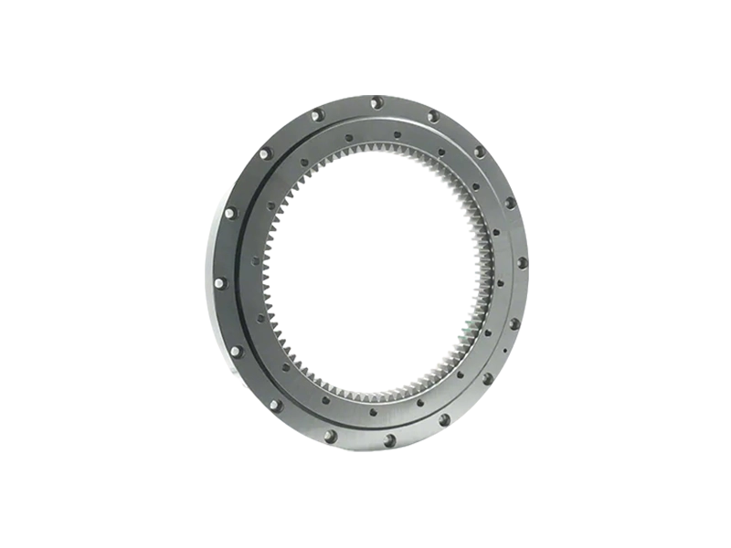
Crossed Roller Bearings
Crossed roller bearings consist of cylindrical rollers arranged in a cross pattern—typically with alternating rollers oriented at 90 degrees to each other within a single raceway. This unique design enables the bearing to handle radial, axial, and moment loads simultaneously from any direction. The rollers are separated by spacers (or a retainer) to prevent friction between them. Because the contact surface between the roller and raceway is a line (rather than a point), the load capacity per unit area is high. PRS offers crossed roller bearings in both inner-ring rotation and outer-ring rotation configurations, with options for integral sealing and preload adjustment.
Angular Contact Ball Bearings
Angular contact ball bearings feature balls running on raceways that are angled relative to the bearing axis. This angle (typically 15°, 25°, or 40°) allows the bearing to accommodate combined radial and axial loads. They are usually used in pairs (back-to-back, face-to-face, or tandem) to achieve bidirectional thrust capacity and increased rigidity. The contact between the ball and raceway is a point, which results in lower friction but also lower load capacity compared to roller bearings of similar size. Angular contact bearings are widely used in high-speed spindles and precision mechanisms where low heat generation is critical.
2. Load Capacity and Stiffness Comparison
The most decisive difference between these two bearing types lies in how they handle loads, particularly moment (tilting) loads and combined loads.
…
For more information on the main differences between crossed roller bearings and angular contact bearings, please click to visit:https://www.prsbearings.com/a/news/difference-between-crossed-roller-bearings-and-angular-contact-bearings.html