Troubleshooting the hydraulic system of a tunnel lining trolley involves a systematic approach, starting with basic checks and progressing to more complex diagnostics. The most common issues relate to pressure, temperature, and contamination.

Tunnel Lining Trolley Hydraulic System Troubleshooting Guide

tunnel lining trolley

Part 1: Understanding the Basic Components

To troubleshoot, you need to know what you’re looking at. A typical tunnel lining trolley hydraulic system includes:

Hydraulic Power Unit (HPU):

Reservoir (Tank): Holds the hydraulic fluid.

Electric Motor or Diesel Engine: Drives the pump.

Hydraulic Pump: Creates the flow of fluid.

Filters: Clean the fluid (suction, pressure, and return lines).

Heat Exchanger (Cooler): Prevents the fluid from overheating.

Control Valves:

Directional Control Valves: Direct the fluid to the correct actuator (often solenoid-operated).

Pressure Relief Valve: The system’s primary safety valve, it opens to send fluid back to the tank if pressure gets too high.

Flow Control Valves: Regulate the speed of actuators.

Check Valves & Pilot-Operated Check Valves: Allow flow in one direction and are used to lock cylinders in place.

Actuators:

Hydraulic Cylinders: Perform the work (lifting/lowering the gantry, expanding/retracting the formwork, propulsion, steering).

Conductors:

Hoses and Pipes: Transport the fluid.

Part 2: The Systematic Troubleshooting Approach

Don’t just start replacing parts. Follow a logical process.

Step 1: Gather Information & Observe

What is the exact problem? (e.g., “The main lift cylinders won’t extend,” “The whole system is slow,” “The pump is making a loud screaming noise.”)

When did it start? Was it a sudden failure or a gradual decline in performance?

More detailed information on how to troubleshoot the hydraulic system of the tunnel lining trolley can be found at: https://www.gf-bridge-tunnel.com/a/blog/troubleshooting-of-hydraulic-system-of-tunnel-lining-trolley.html

Improving the efficiency of tunnel lining construction is a multifaceted challenge that requires a holistic approach, from initial design to on-site execution. Key strategies focus on technological innovation, process optimization, and a highly coordinated workforce.

How to improve the efficiency of tunnel lining construction

tunnel lining trolley

1. Optimize Design and Materials

Select the Right Lining Method: The choice between a precast segmental lining and a cast-in-place concrete lining is the most fundamental decision.

Precast Segments: Ideal for long, straight tunnels, especially in soft ground. Segments are manufactured off-site in a controlled environment, which ensures high quality and allows for simultaneous production and excavation, greatly speeding up the overall project.

Cast-in-Place (CIP): Often more suitable for complex geometries, short tunnels, or areas where ground conditions make precast segments impractical. The use of advanced, fully automated tunnel lining trolleys can significantly increase the speed and precision of CIP construction.

Innovate with Concrete Mixes:

Fiber-Reinforced Concrete: Adding structural fibers (e.g., steel or synthetic) can partially or completely replace traditional steel bar reinforcement. This reduces the time and labor required for rebar placement and can also improve the concrete’s tensile strength and durability.

High-Performance Concrete: Utilizing high-early-strength concrete with chemical admixtures can reduce the curing time required before formwork stripping and segment handling, accelerating the construction cycle.

Self-Compacting Concrete (SCC): This highly fluid concrete flows easily into the formwork, even around complex reinforcement, without the need for vibration. This saves time, reduces labor, and improves the final quality of the lining by eliminating honeycombing.

Implement Integrated Design: Design the tunnel and its lining from a “constructability” perspective. This includes using numerical modeling and Finite Element Analysis (FEA) to simulate construction stages, identify potential issues, and optimize the lining thickness and reinforcement to be both safe and efficient.

2. Leverage Advanced Machinery and Automation

Utilize Fully Automated Formwork Systems: The tunnel lining trolley is the heart of the operation.

Telescopic and Hydraulic Systems: Modern trolleys with telescopic formwork and hydraulic systems allow for rapid advancement and precise positioning. They can be operated by a small crew, reducing manual labor and the risk of error.

Integrated Functions: Look for trolleys that combine multiple functions, such as formwork stripping, moving, and re-erecting, into a single, automated cycle.

Adopt Smart Technologies and Robotics:

Automation: Integrate automation for concrete pouring, vibration, and curing to ensure consistency and speed.

Real-time Monitoring: Use sensors and monitoring systems to track concrete strength, temperature, and pressure. This data allows for real-time adjustments and ensures that the lining meets quality specifications, preventing costly rework.

Robotics: Robotic systems can be used for repetitive or hazardous tasks like shotcrete application, surveying, or handling materials, which improves safety and consistency.

3. Streamline On-site Processes

tunnel lining trolley

Optimize Logistics and Supply Chain:

Just-in-Time Delivery: Coordinate with concrete suppliers and precast segment manufacturers to ensure materials are delivered precisely when needed. This minimizes on-site storage space and reduces potential material degradation.

More detailed information on how to improve tunnel lining construction efficiency can be found at: https://www.gf-bridge-tunnel.com/a/blog/improving-tunnel-lining-construction-efficiency.html

tunnel lining trolley, also known as a tunnel formwork system, is a specialized piece of equipment essential for the secondary concrete lining of a tunnel. The selection of the correct trolley is a critical decision that directly impacts the safety, efficiency, and quality of a tunnel project. The main factors to consider when choosing a tunnel lining trolley are the tunnel’s geometry, the construction method, the required production rate, and the level of automation.

Tunnel Lining Trolley Selection Guide

tunnel lining trolley

Introduction: What is a Tunnel Lining Trolley?

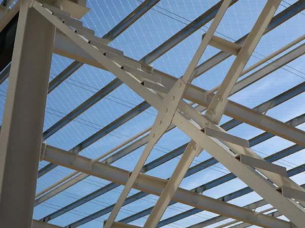
A Tunnel Lining Trolley, also known as a formwork gantry or shuttering carriage, is the backbone of the cast-in-situ concrete lining process in tunnels. It is a large, mobile steel structure designed to:

Support the Formwork: It holds the steel molds (forms) in the precise shape of the tunnel’s final concrete lining.

Facilitate Concrete Placement: It provides access and infrastructure for pouring concrete into the cavity between the formwork and the excavated rock/soil surface.

Strip and Advance: After the concrete has cured, the trolley hydraulically retracts the formwork (strips it) and moves itself forward to the next section to repeat the process.

Selecting the right trolley is not just a procurement decision; it is a critical engineering choice that directly impacts project speed, quality, safety, and budget. A poorly chosen trolley can lead to construction delays, poor concrete finish, and significant safety hazards.

Types of Tunnel Lining Trolleys

Tunnel lining trolleys can be broadly classified based on their function, design, and the type of lining they install.

Cast-in-Place (CIP) Trolleys: These trolleys support formwork into which concrete is poured to create a seamless, monolithic tunnel lining.

Telescopic Formwork Trolley: The most common type for long tunnels, the formwork sections retract or “telescope” inwards after the concrete has cured, allowing the entire trolley to pass through the newly cast section and move to the next work area without being dismantled.

Full-Round Formwork Trolley: This type carries formwork for the entire tunnel cross-section (invert, walls, and arch) and allows for a single concrete pour, making it ideal for circular or near-circular tunnels.

Arch Formwork Trolley: This trolley is used when the tunnel invert (floor) is cast separately. It carries the formwork for the upper arch and sidewall sections and is commonly used for horseshoe-shaped tunnels.

For more detailed information on the tunnel lining trolley selection guide, please click here: https://www.gf-bridge-tunnel.com/a/blog/tunnel-lining-trolley-selection-guide.html

Improving tunnel lining quality involves a combination of careful design, material selection, and rigorous construction and monitoring practices. The quality of a tunnel lining is crucial for its long-term stability, durability, and safety. A poor-quality lining can lead to issues like cracks, leaks, and structural degradation over time.

How to improve tunnel lining quality

Tunnel Lining Formwork

Pre-Construction and Design

A high-quality tunnel starts with a solid plan before any digging begins.

Thorough Geotechnical Investigation: Before construction, a detailed investigation of the ground conditions is essential. This includes understanding the rock or soil type, groundwater levels, and potential for seismic activity. This data informs the design and helps select the most suitable lining method and materials.

Optimal Design: The tunnel lining design must be optimized to handle anticipated loads from the surrounding rock and soil. Advanced techniques like numerical modeling (e.g., Finite Element Analysis) can simulate complex ground-lining interactions to create a reliable and less conservative design.

Material Selection

The materials used for the lining are a major factor in its quality. The right materials enhance durability and structural integrity.

High-Performance Concrete (HPC): Using HPC with improved mechanical properties, such as higher compressive strength and lower permeability, makes the lining more durable and resistant to harsh environmental conditions.

Fiber-Reinforced Concrete: The addition of fibers (steel, carbon, or synthetic) to concrete, especially in shotcrete, enhances its tensile strength, ductility, and crack resistance.

Waterproofing: Incorporating waterproofing measures like membranes and gaskets is critical to prevent water ingress, which can cause erosion, rebar corrosion, and structural instability.

More detailed information on how to improve tunnel lining quality can be found at: https://www.gf-bridge-tunnel.com/a/blog/how-to-improve-tunnel-lining-quality.html

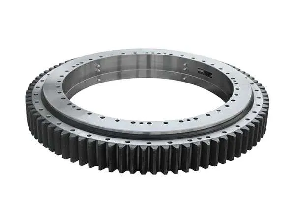
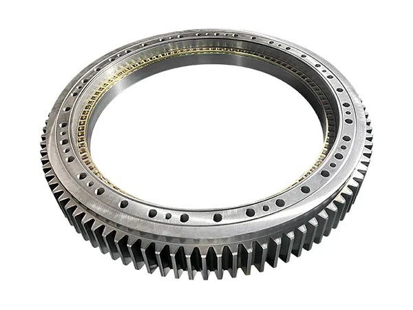
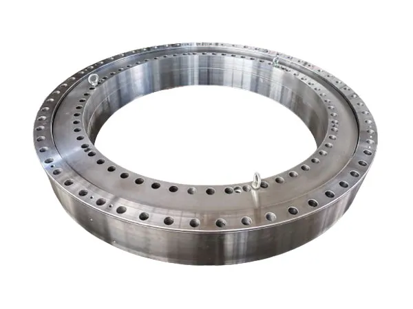
Replacing a trailer turntable bearing is a precise job that requires the proper tools and a safe working environment. The process is a bit more involved than replacing a standard wheel bearing because the turntable bearing is a large, flat slewing ring bolted to both the trailer’s A-frame and its chassis.

Trailer Turntable Bearing Replacement

trailer turntable bearing

Safety First

Secure the Trailer: Before you begin, you must ensure the trailer is stable. Use a jack to lift the trailer and then place it on jack stands to prevent it from moving or falling.

Prevent Movement: Block the wheels to ensure the trailer cannot roll in either direction.

Part 1: Diagnosis & Preparation

Symptoms of a Failing Turntable Bearing:

Before you start, confirm the bearing needs replacement. Common signs include:

Grinding or Popping Noises: Especially when turning the trailer (e.g., in a yard).

Excessive Play or Sloppiness: If you can rock the front of the trailer side-to-side more than a tiny amount, the bearing is worn.

Binding or Stiff Turning: The turntable feels “notchy” or is difficult to rotate.

Metal Shavings: Finding metal flakes around the turntable seals is a sure sign of internal failure.

Uneven Wear on Tires: A failing turntable can affect alignment and tire wear on the dolly or tractor.

Tools and Parts Needed:

Heavy Equipment:

Overhead crane, heavy-duty forklift with lifting rig, or multiple high-capacity (20+ ton) hydraulic jacks and certified heavy-duty support stands.

Impact wrench (1″ drive is recommended for stubborn bolts).

Large torque wrench capable of reaching 500+ ft-lbs (check manufacturer specs).

Hand Tools & Supplies:

Complete socket and wrench set (large sizes).

Long breaker bars and pry bars.

More detailed information on how to replace the trailer turntable bearing can be found at: https://www.mcslewingbearings.com/a/news/trailer-turntable-bearing-replacement.html

Lubricating a trailer turntable bearing is a critical part of a trailer’s regular maintenance schedule. Proper lubrication ensures the bearing operates smoothly, reduces friction and wear, and prevents corrosion, ultimately extending its lifespan and maintaining the safety of the trailer.

Trailer Turntable Bearing Lubrication Guide

trailer turntable bearing

Here is a general guide to lubricating a trailer turntable bearing. Always refer to the manufacturer’s specific instructions and recommendations, as procedures and lubrication requirements can vary by model.

1. Understand the Type of Bearing and Lubricant

Turntable Bearings vs. Wheel Bearings: Be aware that the lubrication process for a turntable bearing is different from that for wheel bearings. While both require grease, the application and frequency are distinct.

Lubricant Specification: Most trailer turntable bearings require a high-quality, lithium-saponified grease. A common and effective choice is an NLGI class 2 grease. Some manufacturers, like JOST, specify their own high-performance lubricants. Always check the manufacturer’s manual for the correct type of grease.

“Low-Maintenance” Turntables: Some modern turntable models are designed to be “low-maintenance” and may not require lubrication for a much longer period (e.g., up to three years or 300,000 km). These are often distinguished by specific markings, such as a green type plate or a “W” in the item number. After this period, they should be serviced like standard turntables.

2. Lubrication Procedure

Locate the Grease Nipples: Turntable bearings have multiple grease nipples (also known as zerk fittings) located around the circumference of the bearing. These are the points where you will inject the grease. Some models have a centralized lubrication manifold to make the process easier.

Attach Grease Gun: Connect a grease gun with the specified grease to the first grease nipple.

Start Pumping and Rotate: As you begin to pump the grease, slowly rotate the trailer’s A-frame or the turntable itself. This is crucial for distributing the grease evenly throughout the ball race and creating a complete “collar” of grease.

Observe for Old Grease: Continue pumping until you see fresh grease extruding from the gap between the two rings of the turntable. This indicates that the old, potentially contaminated grease has been flushed out and replaced with new, clean grease.

Clean Excess Grease: Wipe away any excess grease that comes out. While the grease collar is important for sealing the bearing against dirt and water, you don’t want a thick, sticky layer on the outside that will attract more grime.

More detailed information on trailer turntable bearing lubrication guide can be found at:https://www.mcslewingbearings.com/a/news/trailer-turntable-bearing-lubrication-guide.html 

Trailer turntable bearings, also known as fifth-wheel bearings, are critical components for the safe and smooth operation of a trailer. Proper maintenance is essential to prevent costly repairs and ensure longevity. Neglecting its maintenance can lead to premature failure, costly repairs, vehicle downtime, and severe safety hazards.

Trailer Turntable Bearing Maintenance Tips

Trailer Turntable Bearings

1. Regular Inspection:

Visually inspect the bearing for any signs of damage, such as cracks, rust, or excessive wear.

Check for proper lubrication. The bearing should have a consistent, healthy layer of grease.

Listen for unusual noises during turns or when the trailer is in motion, as this can indicate a lack of lubrication or a failing bearing.

2. Proper Lubrication:

Grease Type: Use a high-quality, lithium-based or marine-grade grease specifically designed for heavy-duty applications.

Frequency: Lubrication frequency depends on the usage and environmental conditions. As a general rule, re-grease the turntable every 10,000 to 20,000 miles, or at least every six months. For trailers used in harsh conditions (e.g., off-road, frequent exposure to water or dust), more frequent lubrication is necessary.

Application: Use a grease gun to apply fresh grease until the old, contaminated grease is pushed out. Ensure the grease is evenly distributed throughout the bearing.

3. Cleaning:

Before re-greasing, it is often a good practice to clean the bearing to remove old, contaminated grease and any debris.

For more detailed information on trailer turntable bearing maintenance tips, please click here: https://www.mcslewingbearings.com/a/news/trailer-turntable-bearing-maintenance-tips.html

Installing a trailer turntable bearing correctly is a critical process that ensures the safety and longevity of your trailer. It’s a complex task that requires attention to detail and following the manufacturer’s specific instructions. However, there are some general best practices that apply to most installations.

Trailer Turntable Bearing Installation

Trailer Turntable Bearing

1. Preparation and Inspection

Inspect the mounting surface: Before you begin, the mounting surface on both the A-frame and the trailer chassis must be completely flat, rigid, and free of any debris, burrs, or paint thicker than 50 mm. Any unevenness (max. 1 mm) can be corrected with shims or plastic metal.

Check the bearing: Ensure the new bearing is the correct type and size for your trailer and that it’s in good condition. The bearing may have a “soft zone” marked with an “S.” This soft zone should be positioned in a non-load or non-constant load area during installation.

Gather your tools: You’ll need high-tensile bolts (grade 8.8 or higher), a torque wrench, and potentially a special tool for pressing in cups or seals, depending on the bearing type.

2. Mounting the Bearing

Never weld the bearing: The turntable bearing itself should never be welded to the trailer frame or A-frame. Welding can damage the bearing and compromise its integrity.

Positioning: The lower ring of the turntable is typically bolted to the A-frame, and the upper ring is bolted to the trailer chassis.

Bolting: Use a minimum of 8 high-tensile bolts per flange. For smaller bearings, 4 to 6 bolts may be sufficient. The mounting bolts should be tightened in a crosswise pattern to ensure even pressure.

Torque: Tighten the bolts to the manufacturer’s specified torque. The pre-tensioning force on the bolts should be approximately 70% of the bolt material’s yield limit. Using a leveling washer is recommended, and spring washers should be avoided.

Shear load: To relieve shear load on the mounting bolts, it’s recommended to weld at least four blocks immediately next to each flange.

Trailer Turntable Bearing

3. Lubrication

Pre-lubrication: Many new turntable bearings are supplied with a base coating of lubricant, but they must be thoroughly re-lubricated before the trailer is put into operation for the first time.

Grease type: Use a high-quality ball bearing grease, typically a lithium-saponified grease of NLGI class 2.

For more detailed information on how to correctly install the trailer turntable bearing, please click here: https://www.mcslewingbearings.com/a/news/trailer-turntable-bearing-installation.html

Choosing a suitable wind tower welding production line is a complex process that depends on several key factors related to your production requirements, financial constraints, and site-specific conditions. The primary goal is to find a system that maximizes efficiency and quality while being cost-effective.

Wind Tower Welding Production Line Selection

wind tower welding production line

Phase 1: Foundational Analysis & Defining Your Requirements

Before you even look at a single piece of equipment, you must clearly define your operational needs.

1. Production Capacity & Takt Time

Target Output: How many towers (or tower sections/cans) do you need to produce per week, month, or year? This is the single most important factor.

Takt Time: Calculate the maximum time allowed to produce one unit to meet demand. This will determine the required welding speed and level of automation.

Shift Patterns: How many shifts will you run per day? A two-shift operation needs a more robust and faster line than a single-shift operation for the same annual output.

2. Tower Specifications (Current & Future)

Diameter Range: What is the minimum and maximum diameter of the tower sections you will produce? This dictates the size of your rolling machines and turning rolls.

Plate Thickness Range: What are the minimum and maximum steel plate thicknesses? This determines the required power of the welding sources, the choice of welding process (e.g., single-wire SAW vs. tandem or multi-wire SAW), and the power of the plate rolling machine.

Section Length: What is the standard length of a single “can” or section? This influences the length of the welding manipulators and the workshop layout.

Material Type: What grade of steel will you be using (e.g., S355, S460)? Different materials have different welding requirements.

Future Trends: Are towers getting taller, thicker, or using higher-strength steel? Plan for the future. Buying a line that is maxed out on day one is a poor investment. Consider a 5-10 year outlook.

3. Workshop Layout & Logistics

Available Space: Map out your facility. Consider the footprint of the entire line, including space for plate storage, work-in-progress (WIP), and finished section storage.

Ceiling Height & Crane Capacity: Do your overhead cranes have sufficient height and lifting capacity to handle the largest and heaviest tower sections? This is a frequent bottleneck.

Material Flow: Design a logical, linear flow from raw plate delivery to finished section painting and shipping to minimize handling time and costs.

4. Desired Level of Automation

Manual: Operator-intensive, suitable for very low volume or custom work. Not recommended for modern tower production.

Semi-Automated: A mix of automated welding processes with manual setup and positioning. A common and flexible choice.

Fully Automated: Integrated systems with CNC control, automated material transfer, laser seam tracking, and data logging. Higher initial cost but delivers the best consistency, speed, and lowest labor cost per unit.

wind tower welding production line

Phase 2: Key Equipment Stations & Selection Criteria

A typical wind tower production line is a series of specialized stations. Here’s what to look for in each.

1. Plate Preparation Station

Function: Cutting plates to size and creating the weld bevels (V, X, or U grooves).

Key Equipment: CNC Plasma/Oxy-fuel Cutting Machine with a milling or plasma beveling head.

Selection Criteria:

Precision: High-precision cutting is essential for good fit-up and weld quality.

Beveling Capability: The ability to create accurate, consistent bevels in a single pass saves enormous time.

Table Size: Must accommodate your largest plates.

2. Plate Rolling Machine

Function: Forming the flat plates into cylindrical or conical “cans.”

Key Equipment: 4-Roll Plate Bending Machine.

Selection Criteria:

Capacity: Must be rated for your maximum plate thickness and width.

4-Roll vs. 3-Roll: A 4-roll machine is superior for tower production. It allows pre-bending of the plate ends, minimizing the flat-end section and requiring less follow-up work.

For more detailed information on how to choose a suitable wind turbine tower welding production line, please click here: https://www.bota-weld.com/en/a/news/wind-tower-welding-production-line-selection.html

Performing daily maintenance on a wind tower welding production line is critical for ensuring safety, weld quality, equipment longevity, and maximizing uptime. A breakdown can halt the entire production process, which is incredibly costly.

Core Principles of Daily Maintenance

Safety First, Always: All maintenance activities must begin with safety. This includes using proper Personal Protective Equipment (PPE) and strictly following Lockout/Tagout (LOTO) procedures for any task that involves potential energy release.

Operator Involvement: The machine operators are the first line of defense. Train them to perform these daily checks as part of their pre-shift routine. They are most familiar with the normal sounds and operations of their equipment.

Cleanliness is Key: A clean work area and clean equipment make it easier to spot leaks, cracks, or other potential issues.

Consistency and Documentation: Perform these checks at the same time every day (e.g., at the start of the first shift). Use a checklist (digital or paper) to log findings, track issues, and ensure nothing is missed.

Daily Maintenance Checklist for a Wind Tower Welding Line

wind tower welding production line

This checklist is broken down by the major components of a typical production line, which often uses Submerged Arc Welding (SAW) for the main longitudinal and circumferential seams.

Part 1: Pre-Shift Area Walk-Through (5-10 Minutes)

This is a high-level visual inspection before starting any equipment.

General Housekeeping:

Floor is clear of obstacles, trip hazards, and spills (especially oil or grease).

All safety guards, barriers, and emergency stops are in place and unobstructed.

Adequate lighting in all work areas.

For more detailed information on daily maintenance of wind tower welding production line, please click here: https://www.bota-weld.com/en/a/news/daily-maintenance-of-wind-tower-welding-production-line.html