There are many auditorium chairs and cinema chairs in the market, and people are dazzled at the exhibition, and there is no way to start when choosing. What are the specific styles of auditorium chairs and theater chairs? For those who don’t understand, they are the same except for the appearance. They don’t know how to identify the quality and where to choose. In fact, auditorium chairs and cinema chairs are classified from bottom to top. Looking down at the feet, auditorium chair tripods can be divided into aluminum alloy feet and iron feet.
Aluminum alloy feet: The aluminum alloy feet are made of aluminum alloy materials, which are light in weight and are not easy to corrode in a humid environment; they will not deform or crack in a high temperature environment; the service life is relatively long, which can meet the different needs of customers (bending or pulling straight).
Iron feet: The iron feet are hard, heavy, and brittle. The surface is electroplated and easy to rust.
Looking at the seat back outer panel, the outer panel is divided into paint panel and plastic shell.
Painted board: The high-quality multi-layer board is cold-pressed by a mold and painted to prevent cracking effectively.
Plastic shell model: The plastic back shell is made of high-quality PP (polypropylene) multi-element conforming material and is molded by injection molding, with a thickness of 3mm. The seat rubber shell is made of high-quality PP (polypropylene) multi-element conforming material by injection molding, with a thickness of 4-6mm. With a muffler hole, it can effectively remove ambient noise.
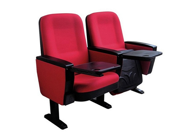
According to the above description, auditorium chairs can be roughly divided into 4 categories: aluminum alloy paint models, aluminum alloy plastic shell models, iron foot paint models, and iron foot plastic shell models.
We have a certain understanding of the types of auditorium chairs through the above, but after all, professional people are in the minority, how to distinguish the quality of auditorium chairs?
…
For more details click to visit:https://www.aoyangschoolfurniture.com/aoyang-news/auditorium-chair-quality-identification-method.html