Worm gear slewing drive and spur gear slewing drive are both highly integrated modular rotary reducers. Users do not need to purchase individual parts one by one and then assemble them into products with worm gear slewing drive and spur gear slewing drive functions. Reduce unnecessary production preparation procedures, greatly improve production efficiency. In a sense, the spur gear slewing drive can replace all toothed slewing bearings. Compared with slewing bearings, it has the advantages of simple installation, easy maintenance, and greater saving of installation space.

So, what are the similarities and differences between the worm gear slewing drive and the spur gear slewing drive in the design and use?

1. Similarities:

Both the worm gear slewing drive and the spur gear slewing drive use the slewing ring as the main moving part. The slewing ring plays the role of driving the equipment to rotate and bearing the equipment load. The worm or gear is used as the driving part of the power input, the housing, the flange, the general support Bearings, seals, etc., as accessories, can finally achieve 360° rotation through reasonable design and assembly, can withstand large loads, and are components with deceleration function. Both types of slewing drives have the characteristics of slewing, deceleration, load-bearing, compact structure, fully sealed, dustproof and waterproof, modular design, and convenient installation and maintenance.

2. The difference:

1. The worm gear slewing drive uses a worm to drive the slewing support to rotate, and the spur gear slew drive uses a gear to drive the slewing support to rotate.

2. The reduction ratio of the worm gear slewing drive is large, and the reduction ratio of the spur gear slewing drive is small.

In the case of the same modulus and the same outer diameter, the reduction ratio of the worm gear slewing drive is equal to the number of teeth of the slewing ring; the reduction ratio of the spur gear slewing drive is equal to the number of teeth of the slewing ring/the number of gear teeth. The number of teeth of the gear is generally designed to be 15 teeth, and reduce The difference is 15 times.

3. The worm gear slewing drive has the characteristics of reverse self-locking, and the spur gear slewing drive cannot be reversed self-locking.

The worm gear slewing drive can only be driven by the worm to rotate the worm wheel, and the worm cannot be driven by the worm gear to rotate. The reverse self-locking makes the slewing drive widely used in lifting equipment, high-altitude operations and other equipment. Under such working conditions, the worm gear slewing drive is used No braking device is required, and the equipment can remain stationary for a long time without power. The spur gear slewing drive gear can drive the gear ring to rotate, and the gear ring can also drive the gear to rotate in reverse. It cannot achieve reverse self-locking. This feature is also used in some special fields, such as wood grabbers, snow sweepers, etc. Collision cannot be avoided during the use of the equipment, and it does not self-lock when a collision occurs, which acts as a buffer and protects the equipment.

4. The worm gear slewing drive has a low speed limit, and the spur gear slewing drive has a high speed limit.

The worm gear slewing drive is a worm gear drive, and the worm gears slide between each other. High-speed rotation is easy to generate heat, causing the worm to overheat and lock or directly damage. Generally, the rotation speed of the worm gear slewing drive does not exceed 2.5 rpm; gear type slewing drive It is the tooth-to-tooth meshing that works, it is not easy to generate heat, and the speed can usually reach 40-60 rpm.

5. The transmission efficiency of the worm gear rotation drive is low, and the transmission efficiency of the spur gear rotation drive is high.

The worm gear slewing drive has high friction between the worm wheel and the worm, and the transmission energy loss is large, so the transmission efficiency is low, usually only 30%-40%; the friction resistance between the spur gear slewing drive gears is small, and the loss is small, so the transmission efficiency is high. Generally, it can reach 90%-95%, which is very efficient and energy-saving.

6. The worm gear slewing drive has low slewing accuracy, and the spur gear slewing drive has high slewing accuracy.

The rotation accuracy of the ordinary worm gear slewing drive is affected by various factors, and can not achieve a small backlash. Generally, the precision of the precision type can reach within 0.05°; the spur gear rotation drive has high rotation accuracy, and the gears and ring gears can be grounded. The processing method can achieve high precision, and the precision of the gear type rotary drive with a diameter of 1 meter can reach within 0.01°.

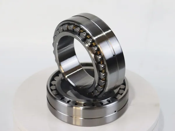
The double-row ball slewing bearing is called “mechanical joint” in the machinery industry. It is the primitive mechanical transmission necessary for relative rotation between two objects, and can bear axial force, radial force and overturning moment.

Heat treatment of double-row ball slewing ring bearings and gears:

The raceways of the double-row spherical slewing ring are surface induction hardened, and the hardening hardness ensures that the depth of the hardened layer can be reached under HRC55 to 62.

Due to the need for transmission, the double-row ball slewing ring is usually made of one of the rings. The heat treatment state of the gear is usually normal or quenched and tempered. The tooth surface can also be quenched according to user requirements, and the quenching hardness is HRC50~60, which can ensure sufficient depth. According to different applications, gear quenching can be divided into full-tooth quenching and single-tooth induction quenching. Single tooth induction hardening can be divided into tooth surface tooth root quenching and tooth surface quenching.

Double-row ball slewing bearing, adapt to temperature and working environment:

Slewing-Bearings

The double-row ball type slewing bearing can work at a temperature of -300C~700C. Users need to adapt to lower or higher temperature double-row ball slewing bearings. The double-row ball slewing ring is the same as other ordinary bearings. They have rolling bearings and races, but they are different. The double-row ball slewing bearing has many different characteristics.

The size of the double-row ball slewing bearing is relatively large, usually 0.2-10 meters in diameter, and some can even reach 40 meters.

Generally, the double-row ball slewing bearing must not only bear the axial force and the radial force, but also bear a greater overturning moment, so as to bear a variety of loads. Therefore, a set of double-row ball slewing bearings usually play the role of several sets of ordinary rolling bearings.

The double-row ball slewing ring runs at a lower speed, usually 50 rpm. In many cases, the double-row ball slewing ring cannot work continuously, but can only operate at a rotation angle (equivalent to the so-called “slewing bearing”).

In the manufacturing process such as materials and heat treatment, double row ball slewing bearings and rolling bearings are also very different.

Generally, the double-row ball slewing bearing has a gear ring for rotating drive and a sealing device for dust prevention.

The installation method of the double-row ball slewing bearing is different. It is not like ordinary spindle bearings, but installed in the bearing box, but fixed in the upper and lower bearings by screws.

The double-row ball type slewing ring is also called “slewing ring” because its shape is similar to that of a plate, so it can bear the comprehensive load of a large bearing. It can also withstand greater axial loads, radial loads and overturning moments. Used in combination with ordinary bearings. Use function. Usually suitable for bearing huge overturning moment and relative rotation of mechanical equipment. It is an efficient and high load bearing combined bearing.

Therefore, due to the special nature of the double-row ball slewing bearing, the double-row ball slewing bearing has been applied to a large extent.

The micro sample nucleic acid extraction kit is a kit specially used to extract DNA and RNA from various micro and trace samples. This kit uses a centrifugal adsorption column that can specifically bind nucleic acids and a unique buffer system. After the sample is lysed, the DNA is specifically bound to the silica gel membrane under high salt conditions, and the DNA is washed from the silica gel membrane at low salt and high pH. Take it off.

This kit is used to extract genomic DNA and mitochondrial DNA from small amounts of blood, dried blood spots, chewing gum, swabs, urine, and small amounts of tissues. It can also be used to purify genomic DNA obtained from other methods. DNA can be directly used as PCR template, enzyme digestion, hybridization and other molecular biology experiments.

Features of Micro Sample Nucleic Acid Extraction Kit

1. The recovery rate of nucleic acid is high, which can reach more than 90%

2. One-tube operation reduces the possibility of sample contamination.

3. One-stop kit, customers do not need to prepare any reagents except samples, which reduces experimental errors.

4. Safe and non-toxic, no need to use organic solvents such as phenol and chloroform.

5. It can handle samples of various forms, including liquid samples, single or small amount of cells, tiny embryos and so on.

6. Compatible with PCR, fluorescent PCR, RT-PCR, fluorescent RT-PCR and other follow-up reactions.

7. The reagent is stable and can be stored for a long time.

Nucleic acid extraction system, also called nucleic acid purification instrument, is an instrument that uses matching nucleic acid extraction reagents to automatically complete sample nucleic acid extraction. An instrument that has only been applied and promoted in recent years.

Nucleic acid extraction system application field

In almost every laboratory, the separation and purification work related to biomolecules is very important and indispensable. However, it is still quite difficult to purify multiple samples. It is not only necessary to select a suitable purification technology, but also the workload is particularly large, which is difficult to meet the current rapid development of high-throughput sample extraction and purification needs. The magnetic bead automatic nucleic acid extraction and purification system uses magnetic bead technology, which can be widely used in genomics, disease control and medical care, food safety, forensic identification and other fields.

Genomics

The automatic nucleic acid extraction system is very suitable for genomics research. Samples can be extracted from microorganisms, animals, plants, or viruses. Whole blood genomic DNA extraction kits, leukocyte layer whole blood genome extraction kits, animal tissue/cell genomic DNA extraction kits, can quickly purify sufficient quantities and Pure DNA or RNA. High-quality nucleic acid can meet the needs of various downstream applications (such as PCR/Real-time PCR, gene chip, Southern blot, Northern blot).

CDC

The automatic nucleic acid extraction system can be used to solve the rapid automatic disease monitoring system of Influenza A virus subtype H1N1, children’s hand, foot and mouth disease, measles virus, etc., and improve the response ability of major epidemics.

Molecular diagnosis of clinical samples

The automatic nucleic acid extraction system can process clinical samples quickly and with high throughput, and the extracted nucleic acid can be used for subsequent molecular diagnosis. It is also suitable for formalin-fixed and paraffin-embedded (Formalin-Fixed and Parrffin-Embedded, FFPE) tissue samples.

Animal Husbandry and Veterinary Medicine

It can extract Avian influenza virus (Avian influenza virus), Newcastledisease virus (Newcastledisease virus), Classical swine fever virus (CSFV), Bovine viral diarrhea virus (Bovine viral diarrhea virus), Rickett. Secondary body (Coxiella burnetii) and so on.

Forensic applications

For forensic work, the efficiency and stability of nucleic acid extraction are very important. The automatic nucleic acid extractor is used in conjunction with a special forensic sample nucleic acid extraction magnetic bead reagent to purify high-quality DNA from materials from different sources including cigarette butts, hair roots, cartilage, nails, and blood stains.

The lining trolley is driven by the driving wheel to wind the crawler and cyclically rotate, and it is a mechanism that supports the body. It is composed of crawler walking device and suspension. The lining trolley walking system often adopts the overall trolley traveling system and the balancing trolley traveling system. The walking device of the lining trolley consists of crawlers, driving wheels, supporting wheels, supporting wheels, tensioning wheels and tensioning buffer devices. The engine transmits the torque to the driving wheels through the transmission system, and drives the crawler belt to move in a circular motion, which becomes an infinitely long moving track carried by itself. There are two types of crawler: metal crawler and metal rubber crawler. The most widely used metal crawlers are combined type and integral type.

It is composed of track, driving wheel, supporting wheel, supporting wheel, tensioning wheel and tensioning buffer device. The engine transmits the torque to the driving wheels through the transmission system, and drives the crawler belt to move in a circular motion, which becomes an infinitely long moving track carried by itself. There are two types of crawler: metal crawler and metal rubber crawler. The most widely used metal crawlers are combined type and integral type. The combined track is composed of track section, track shoe, track pin and pin sleeve. Each track shoe is fixed on the track section with bolts, and each track section is connected to each other by a track pin with a pin sleeve. The track shoe can be made of special-shaped steel such as high-quality carbon steel or alloy structural steel. The combined crawler has high rigidity, good sealing performance and long service life, and different types of crawler shoes can be replaced according to needs.

But it is heavy and inconvenient to disassemble and assemble. The track shoes of the monolithic track are mostly cast from wear-resistant alloy steel, and each track shoe is directly connected to each other with track pins, which has a simple structure, light weight, and convenient disassembly and assembly. However, the gap at the pin hole is large, the sand is easy to enter, and the service life is short. The use of bimetallic track pins with chrome steel surface or track pins with rubber bushings can extend the service life. The metal rubber track uses rubber as a connecting piece, and has two types: block type and whole strip type. Each section of steel spurs is integrated with a rubber block or a whole rubber belt. There is no noise when working, and can alleviate the impact, and has a long service life, but the rubber is easy to age.

The supporting wheel is used to transfer the weight of the lining trolley to the crawler belt and play a supporting role; the tension wheel and the tension buffer device are used to guide the crawler belt to move normally and maintain a certain degree of tightness of the crawler belt. When the tension wheel is impacted, it can slide or swing backwards to alleviate the impact, and adopts screw type or hydraulic type tensioning mechanism. The screw type structure is simple, but the adjustment is laborious; the large and medium-sized lining trolley should adopt a hydraulic tensioning mechanism. The role of the supporting roller is to support the crawler, reduce the amount of sag of the crawler, and prevent the crawler from jumping and lateral slippage. Some supporting rollers use rubber rims to reduce noise and prolong service life.

Tunnel lining construction is the key construction content of tunnel engineering, which is related to construction quality and construction safety. So what are the causes of common problems in tunnel lining construction? What preventive measures are there to ensure the quality of tunnel lining construction? Remember the following 15 points to easily avoid common problems in tunnel lining construction.

Quality issues and phenomena

1. There are voids behind the lining;

2. Obviously staggered lining, serious leakage, quicksand, and poor appearance quality;

3. The thickness of the lining does not meet the design requirements;

4. Water leakage in the lining;

5. The lining concrete is cracked;

6. The appearance quality of the water trench cable trough is poor;

7. Poor drainage of the drainage ditch.

Analysis of the cause of the cavity behind the lining

1. Construction and backfilling of over-excavation that is not in accordance with the specifications;

2. When lining the vault, the pouring concrete is not full and the vibration is not enough;

3. The pumped concrete creates a cavity at the far end of the conveying pipe due to pressure loss, slope and other reasons;

4. The slackness of the waterproof board is not well controlled.

Measures to prevent cavities behind the lining

1. The tunnel excavation surface is inevitably uneven. For the pits caused by over-excavation in a small area, the lining concrete is generally used for backfilling during the construction. Note that the waterproof board should be close to the rock surface and the tightness is suitable; for the collapse caused by landslides For deep sinking pits, use landslide treatment measures to backfill smoothly before the construction of the second lining;

2. The general lining formwork trolley has a reserved hole for pumping concrete at the front and rear of the arch top position. If the formwork trolley is longer, the reserved hole can be added in the middle to prevent the concrete from being poured out of place when the longitudinal slope of the tunnel is large. Backfill grouting after construction;

3. The new lining formwork trolley is equipped with attached vibrators on the side walls and the arch waist. At the same time, two plug-in vibrators are installed on both sides of the trolley during concrete pouring, and the separation is carried out from the reserved window of the trolley. Layer vibrating, these can effectively solve the problem of vibrating.

Analysis of the cause of poor apparent quality of lining

1. The rigidity of the lining trolley is not enough, and the template repair is not in place;

2. The workability of the lining concrete is not good, and the bleeding is serious;

3. No symmetrical pouring on both sides;

4. The pouring speed is too fast and the trolley floats;

5. The template is coated with too much oil, and a fish scale cloud will be formed after the mold is removed;

6. Part of the template is not cleaned up, and the phenomenon of “skinning” and lumps is formed after the mold is removed.

Preventive measures for poor apparent quality of lining

1. Lining trolleys are all processed by regular manufacturers, and the strength and stiffness are checked before processing. Check the calculation data when purchasing;

2. During lining construction, if the overlap of the lining formwork trolley does not exceed 0.5m, misalignment will generally not occur. Therefore, before the lining construction, plan the length of the trolley in place to avoid long overlap. At the same time, the surveying personnel must have certain construction experience, the lining center line and elevation are well controlled, and the offset control on both sides of the formwork trolley is appropriate to prevent the occurrence of too large or too small affecting the next set of trolleys in place;

3. The lining concrete shall be constructed in strict accordance with the designed mix ratio. When designing the mix ratio, the pumping concrete and workability requirements shall be considered. At the same time, the formwork trolley shall be coated with a mold release agent. The mold release agent is best to use a special mold release agent and apply evenly. Moderate dosage can improve the surface quality of the lining;

4. When the lining is poured, both sides should be layered and symmetrically poured, and the concrete falling height should be controlled within 2m to prevent segregation;

5. If there is some concrete sticking to the formwork trolley, clean it up before pouring next time, and then apply a release agent, otherwise it will affect the surface finish of the next set of linings;

6. The lining formwork trolley will float up due to the pressure of the cast-in-place concrete at the foot of the side wall and the end pressure will move longitudinally. Therefore, the formwork trolley is firmly reinforced before the lining construction. At the same time, the lining concrete is poured to the height of the center and the arch waist. The screw is re-reinforced to prevent the trolley from moving due to the loosening of the floating part of the screw.

The lining thickness is not enough, the cause analysis is enough

1. The contractor’s quality awareness is not strict, and the process monitoring is not in place;

2. Or the reserved settlement is insufficient;

3. The under-excavated parts are not processed.

Mmeasures to ensure the thickness of the lining

1. The thickness of the lining should be guaranteed, and the initial support section should be inspected before the construction of the lining. If there is any intrusion into the lining clearance, it should be treated according to the specifications;

2. For some tunnels with large settlements, pay attention to settlement observation. If the designed settlement does not meet the requirements, the reserved amount can be appropriately enlarged according to the actual situation, but it should not be too large to prevent artificial over-excavation. Waste lining concrete.

Analysis of Causes of Water Leakage in Lining

1. The lining is cracked;

2. Waterproof, drainage and water diversion facilities are not perfect;

3. There are quality defects in the treatment of circumferential construction joints and deformation joints, and the installation of water stop strips and water stop belts is not standardized;

4. The waterproof board is damaged, perforated, and the weld is not tight;

5. The lining is not compactly tamped, and there are holes or honeycombs;

6. Unqualified waterproof materials;

7. The number of drain holes is insufficient or the drainage is blocked.

Lining water seepage prevention measures

Lining seepage is generally caused by inadequate waterproof and drainage construction and imperfect lining. It is necessary to strengthen on-site management to ensure that the waterproof and drainage measures are in place, and the concrete lining is poured tightly. The following aspects should be done specifically:

1. Blind pipes are installed in place. Before the waterproof board is constructed, ensure that the blind pipes are installed according to the design requirements. The number of blind pipes should be increased if the water seepage in some sections is large. The blind pipes and the longitudinal drainage pipes are connected well to ensure the drainage effect;

2. Waterproof board construction is the key link of lining waterproofing. At present, there are many types of waterproof boards on the market, and the quality of the waterproof boards must be qualified; the waterproof board connection is best to be welded. During the construction process, quality supervisors will check on site and find problems in time deal with. Part of the uneven areas should be inspected to prevent leakage of welding; for reinforced concrete linings, the waterproof board should be prevented from being damaged during the construction of the steel bars. If there is any damage, the waterproof board construction personnel should be notified to repair; the waterproof board should be installed close to the rock surface , The degree of tightness is moderate to prevent the waterproof board from tearing due to pressure when the concrete is poured;

3. Treatment of construction joints and settlement joints: general construction joints and settlement joints are designed with embedded and embedded waterstops or waterstops, and some have back-attached waterstops, etc. The back-attached type is better for construction and close to The waterproof board can be fixed by the head plate; during the construction of the buried water stop strip, a corresponding size of the small size (half the thickness of the water stop strip) should be reserved in the middle of the lining end, and the water stop strip should be inlaid during the next set of construction. Into, firmly fixed. The construction of the buried waterstop requires the headboard to be constructed in layers, divided into two layers from the location of the waterstop to ensure that the waterstop is reserved and cannot be damaged, which seriously affects the construction of the headboard, so the construction is often not in place. Strengthen the management on site to ensure the construction of the buried waterstop is in place;

4. The horizontal drainage pipe should be reserved according to the design and adopt three-way connection to ensure that the drainage can flow into the ditch smoothly; the longitudinal drainage pipe is generally a perforated corrugated pipe, wrapped with geotextile to prevent the ingress of sediment and affect the drainage effect;

5. There should not be a long pause during the lining concrete pouring process, so the site materials, generators, etc. must be prepared to prevent mid-stop work, because the two pouring concrete is prone to cracks, causing water leakage in the lining; the only solution is to perforate grouting. Water, but the holes should be shallow to prevent damage to the waterproof board;

6. The lining concrete must have a waterproof effect. Generally, it is designed as a waterproof concrete. When designing with it, it must be considered from many aspects. It is necessary to ensure the workability and anti-seepage requirements, and the construction shall be carried out in strict accordance with the cooperation;

7. When pouring the lining concrete, control the concrete falling height to ensure layered pouring, layered vibrating in place, the formwork trolley window formwork is closed tightly to prevent mortar leakage, etc., to ensure the compactness of the concrete lining, and ensure that the construction concrete has a waterproof effect.

Analysis of the causes of lining cracking

1. Temperature difference and concrete shrinkage;

2. Alkali aggregate chemical reaction;

3. The side wall foundation sinks;

4. Hole body bias;

5. The joint part of the invert and the side wall is cracked due to stress concentration;

6. Cracking caused by difficulty in pouring concrete in the arch or interruption of pouring;

7. The demoulding time is too early, and the lining strength is not enough to support its own weight and cracks.

Preventive measures for lining cracking

1. The heat of hydration of high-grade concrete is increased. After construction, it must be sprinkled and maintained for no less than 14 days to prevent the surface from drying and causing cracks;

2. Select qualified materials for lining concrete materials, and construct in strict accordance with the mix ratio;

3. The lining generally does not crack. Generally, the lining is cracked due to bias pressure or terrain movement at the opening of the cave. Therefore, when backfilling the roof of the cave, pay attention to the symmetrical backfilling on both sides. For tunnels with biased pressure, strengthen the lining strength or reduce pressure;

4. The joint part of the invert and the side wall is prone to stress concentration. During construction, ensure that the side wall foot is excavated in place, and there should be no under-excavation, which will cause the lining to crack;

5. Control the demoulding time of the lining, and formulate the demoulding time and curing time according to the different tunnel temperatures in different seasons to prevent the concrete from falling off and cracking;

6. The lining concrete is guaranteed to be poured in place at one time and cannot be stopped halfway. It is not conducive to waterproofing and can easily cause cracks and reduce the strength of the lining. Therefore, the material reserves are sufficient before construction and the machinery and equipment are good; at the same time, the formwork trolley should be checked before the lining construction. There are deformations, loose bolts, welding off, etc., to prevent problems during the construction process, resulting in abnormal lining construction.

Analysis of Causes of Poor Appearance Quality of Cable Trenches

1. The mould is not meticulous and not firm, and the outer edge of the groove is not controlled according to the center line of the line;

2. The cover plate is prefabricated and has poor installation quality;

3. Other process construction, repeated lifting, moving and collision and damage.

Appearance quality control measures of water trench cable trough

The gutter cable trough is a tunnel surface project, and the surface construction quality affects the overall image of the tunnel. Therefore, it is necessary to ensure linearity and straightness, without dislocation and smooth surface.

1. The cable trough of the water ditch is controlled by measuring and laying out, the curve is controlled according to the radius, the height of the center line of 10m or 20m, and the straight line is controlled by 50m. The template adopts an integral steel template to ensure one-time pouring and molding. The template is coated with release agent to ensure the appearance quality. After the template is installed, the technician checks the installation of the template, whether the linearity meets the standard and whether the reinforcement is firm;

2. Cover plate prefabrication adopts centralized prefabrication in the prefabrication yard, adopts shaped steel-plastic template, with marks on the upper and lower sides, which is convenient for installation; the concrete requirements and workability of the cover plate are good, and the vibrating table is vibrated to ensure a smooth surface;

3. After the cover plate is prefabricated, it is stored in the prefabrication yard. After the tunnel trench construction is completed, it is placed in a centralized manner when no other processes are affected. The gap between the cover plate and the foundation is filled with mortar when placing, and the installation is required to be stable and not shake.

 Analysis of Causes of Poor Drainage in Drainage Ditch

1. The vertical slope at the bottom of the ditch is not standardized, there are deviations, and the control is not accurate, and the bottom of the ditch is “wave”;

2. The slope of the longitudinal slope at the bottom of the ditch is small;

3. There are debris in the ditch and the flow path is blocked;

4. The bottom of the ditch is not smooth.

Preventive measures for poor drainage of drainage ditch

1. The trench is excavated in place, and the concrete is poured to ensure linearity and straightness, to ensure the smoothness of the trench and prevent water accumulation;

2. There are many sundries in the tunnel during working hours and it is easy to block the groove, so it should be cleaned regularly to facilitate drainage in the tunnel;

3. Drainage. Because the formwork is installed straight when ditching and pouring, the reinforcement is firm, and the concrete is tamped and compacted when pouring.

There are many commonly used tunnel construction equipment, such as tunnel lining trolleys, excavators, loaders, roadheaders, dump trucks, bulldozers, graders, concrete mixers, asphalt mixing plants, grab machines, conveyors, fans, and dust removal. In addition, more advanced shield machines may also appear in tunnel construction. However, construction equipment is only a part. These construction equipment need to be used with wear-resistant accessories, such as the bucket of the excavator, the bucket of the loader, the bottom plate and liner of the dump truck, the shovel of the bulldozer, the scraper of the grader, Mixer liners and blades, grabs, fan liners, shield machine blades, etc., all need to use a certain strength wear plate according to the environment, such as dump trucks, etc., which require higher wear resistance, such as jfe-c500, jfe-c550 and so on. In addition, the processing and technology of wear-resistant parts can also increase their service life, which can be carried out in specialized wear-resistant steel processing enterprises.

Luoyang Gaofei Machinery, as a professional tunnel construction equipment manufacturer, It is a modernized production of bridge and tunnel complete sets of equipment, integrating design, research and development, production, sales, installation and service. enterprise.

Compared with the gear reducer, the worm gear reducer has a self-locking function. Worm gear reducers for lining trolleys are widely used in the mechanical field because of their self-locking function, such as tunnel lining trolleys, winches, packaging machines, printing machines, conveying equipment, and so on. However, it is also because of the frictional transmission method of the worm gear, which also causes the transmission efficiency of the worm gear to be much lower than that of the gear transmission. This is where the worm gear reducer is insufficient.

worm gear reducer

In the transmission mode of the worm gear reducer, the worm gear transmission has the characteristics that other gear transmissions do not have. That is, the worm can easily rotate the worm wheel, but the worm wheel cannot rotate the worm. This is because the structure and transmission of the worm wheel and worm are realized by friction.

Not all worm gear drives have a good self-locking function. The self-locking function of the worm gear can only be achieved when a certain speed ratio is achieved, and the self-locking effect will be better. This is related to the lead angle, that is, the self-locking function of the worm gear reducer with a small speed ratio is not so ideal.

In order to reduce the occurrence of tank truck loading and unloading accidents, a few precautions for tank truck loading and unloading operations are hereby posted:

1. Safety technical measures:

(1) Reliable electrical connections and grounding should be made between the loading and unloading facilities of automobile oil tank trucks, including crane pipes, oil pipelines, and metal oil loading platforms.

(2) The ground scales, crane pipes, fueling guns, pipelines, etc. of the oil loading and unloading site should be bridged and equipped with electrostatic grounding devices. The grounding resistance is not more than 100Ω.

⑶ The fuel delivery site for automobile tank trucks should be equipped with a copper core soft stranded wire with a cross-sectional area of ​​not less than 4mm2 and one end connected to a paint-breaking alligator clamp, special connecting clamps, etc., so as to be connected to the body of the tank truck; One end should be connected to a grounding device.

⑷Automobile tank trucks used to transport refined oil should use rubber towing belts, and metal towing belts are prohibited.

⑸Baffle plates should be installed in the oil tank of the automobile tanker. It is forbidden to use non-baffle tank trucks to transport easy fuel products.

⑹The resistance between the oil tank and the car body shall not be greater than 106Ω. The resistance value of the conductive path between any two points in the metal pipeline or on the conductive parts inside the oil tank and the end of the mopping tape shall not be greater than 5Ω.

⑺ When the tanker truck is filled with oil, the maximum safe flow rate of crane pipes of different diameters should meet the requirements of the following table.

oil tank truck

Maximum safe fuel filling flow rate of tank car (the number in brackets is the corresponding flow m/s)

Diameter of crane tube

Oil filling method 80 90 100 110 120 150

Top loading 6.0 (110) 5.5 (125) 5.0 (140) 4.5 (155) 4.2 (170) 3.3 (210)

⑻The connection between the electrostatic grounding wire and the tank car should meet the following requirements.

① The connection should be tight and reliable, and winding connection is not allowed.

②Connect before opening the tank lid.

③It should be connected to the special ground terminal board of the tanker, etc., and it is not allowed to connect within 1.5m of the loading and unloading oil port.

④Remove the connection after closing the tank lid.

⑼ During the operation, the light oil products should be loaded and unloaded in strict accordance with the relevant operating procedures. It is strictly forbidden to conduct gauge, temperature measurement, sampling, or insert other objects into the tank after 2 minutes of unstable oil.

⑽ When the tanker uses top-loading oil, the oil-loading crane pipe should go deep to the bottom of the tank, and the distance from the bottom of the tank should not be greater than 200mm. Splashing light oil is strictly prohibited.

⑾Original oil tanks with high volatile oil products (including tankers) should be tested for the concentration of oil and gas in the tank when replacing low volatile oil products. When the concentration of oil and gas exceeds 25% of the lower explosive limit, ventilation or cleaning should be carried out.

⑿In the process of loading and unloading flammable fuel products, no field test or test that may generate static ignition sparks is not allowed without approval.

⒀It is strictly forbidden to wipe and test vehicles, objects or the ground in the workplace, and conduct various temporary operations that may cause static electricity hazards.

2. Safety precautions

1. Operators should wear clothes and shoes that can discharge static electricity.

2. Use tools that do not produce sparks.

3. It is forbidden to work during thunderstorms.

4. Pay attention to observe to prevent oil spills.

5. When oil spills or oil leakage are found, all oil filling operations at the relevant oil filling point and adjacent oil filling positions should be stopped immediately. All valves that are open when unloading or filling the lower part of the oil should be closed. Only key personnel should be left on the oil loading platform. Do not operate the starter of the vehicle until the spilled oil is cleaned up. The oil filling shall not be resumed until the person in charge of oil filling declares that the area is safe.

6. If a fire alarm occurs during oil loading and unloading, all operations should be stopped immediately, and unaffected vehicles should be driven away immediately. Close the oil tank valve to cut off the oil source, and immediately implement fire extinguishing operations.

7. It is not allowed to turn on the ignition switch for a long time after the car is stopped. A car once caught fire on its own in the garage. After investigation, it turned out that the ignition switch was still on after returning from the car last time. If it is turned on for a long time, it will not only cause the battery to discharge for a long time, but also cause the danger of fire.

8. It is not allowed to implement “self-flowing oil supply” for a long time. Sometimes due to the damage of the gasoline pump or the damage of the oil pipe joints, the gasoline pump cannot normally supply fuel to the carburetor, and it cannot be repaired temporarily. Only emergency treatment and self-flow fuel supply can be taken to drive the car back to the yard or drive to repair plant. At present, for the purpose of fire prevention, the road traffic management regulations formulated by the state do not allow this method to be used.

9. Open flames are not allowed to observe the height of the battery liquid level at night. When driving, the battery is in an overcharged state, and the excessive hydrogen accumulated in the shell causes an explosion when it encounters an open flame. Therefore, the small holes on the battery cover must be kept unblocked at ordinary times.

Many people think that there is no difference between a sewage suction truck and a septic tank truck. This is wrong. If you choose the wrong vehicle, it can cause inconvenience after buying the car, spend unnecessary expenses, or even use it, you must be sure before choosing a vehicle It is necessary to figure out your own purpose and use goals, and make clear the purchase of a car. Let me tell you the difference between a septic tank truck and a sewage suction truck.

The septic tank truck and the sewage suction truck have the same principles and are composed of three three principles: the vehicle chassis, the tank body, and the vacuum system. The difference lies in the tank body, so the purpose is greatly different. It can be said that the sewage suction truck can be used as a septic tank truck, but the septic tank truck cannot be used as a sewage suction truck, and it does not have the function of a sewage suction truck. The cost of a septic tank truck is more expensive than a sewage suction truck. Greatly reduce, don’t listen to unscrupulous merchants.

septic tank truck

Septic tank truck and sewage suction truck tank distinction

The tank body of the sewage suction truck adopts a round tank body. The advantage of the tank body can be 45 degrees. The tank body can be lifted by a double hydraulic tripod (no residue on the tank body). The back cover of the tank body can be opened at a right angle of 90 degrees. (There is no restriction on the sewage discharge of the tank body. , As long as there is nothing that can be pumped in, it is mainly used for pumping septic tanks, farm feces, sewage sludge and stones, with thicker sediments and objects with more debris.
The tank body of the septic tank truck adopts an oval tank body. The tank body is integrally sealed and has a simple structure. It is mainly used for pumping septic tank feces and sewage (the tank body has limitations, such as stones, bricks, and non-liquid objects. It is difficult to discharge , Difficult to clean up.)

Both cars are equipped with self-extracting and self-draining devices, which are simple to operate and easy to use. Before you buy a vehicle, you must figure out your purpose. Where is the main job used, such as simply pumping a septic tank, buy a septic tank truck. If the job is diversified, be sure to buy a sewage suction truck to avoid future troubles.