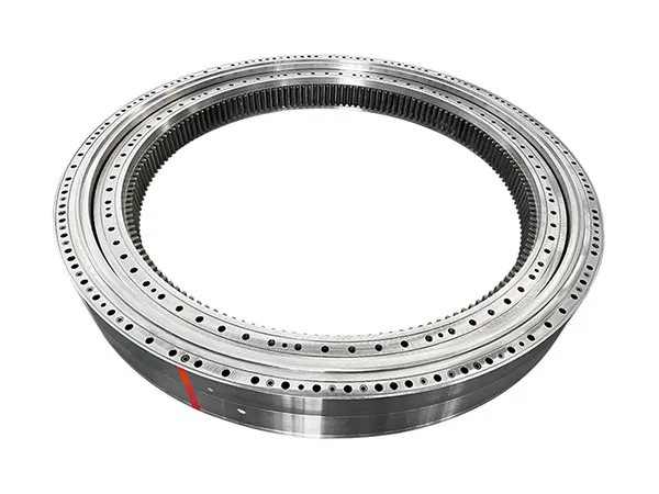
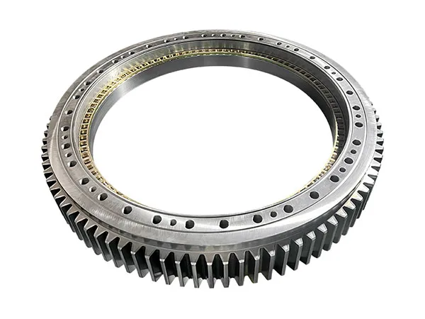
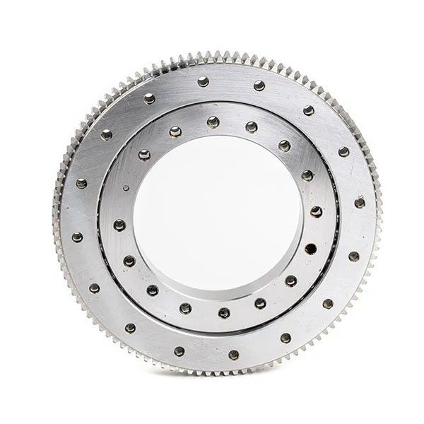
Flange bearings are crucial components in various industrial applications, providing support for rotating shafts while ensuring smooth and efficient movement. Proper lubrication is essential to minimize friction, reduce wear, and extend the bearing’s lifespan. Inadequate lubrication can lead to overheating, premature failure, and increased maintenance costs.Lubricating flange slewing bearings is crucial for their longevity and performance. Here’s a comprehensive guide on how to do it correctly.

Flange Bearing Lubrication
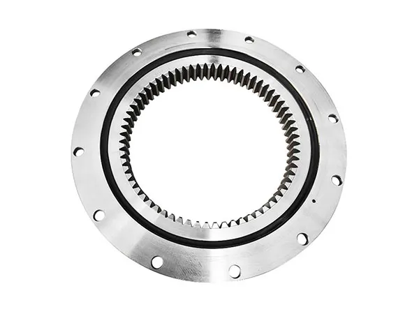
Flange bearings

1. Understanding Your Bearing:

Bearing Type: Different types (e.g., single-row ball, double-row ball, roller) have slightly different lubrication needs. Consult the manufacturer’s specifications.

Seal Type: Bearings often have seals to protect the internal components from contamination. The seal design (e.g., contact seals, labyrinth seals) may influence lubrication procedures.

Operating Conditions: Factors like load, speed, temperature, and environment significantly impact lubrication frequency and grease type.

2. Importance of Proper Lubrication:

Reduced Friction and Wear: Lubrication minimizes friction between the rolling elements (balls or rollers) and the raceways, preventing wear and extending bearing life.

Heat Dissipation: Grease helps dissipate heat generated by friction, preventing overheating and potential damage.

Corrosion Protection: Grease acts as a barrier against moisture and contaminants, protecting the bearing from corrosion.

Sealing: Grease contributes to sealing the bearing, keeping contaminants out and lubricant in.

3. Lubrication Materials (Grease):

Choosing the Right Grease: Select a grease specifically designed for slewing bearings and recommended by the bearing manufacturer. Consider these factors:

Base Oil Viscosity: Higher viscosity for heavy loads and slow speeds, lower viscosity for lighter loads and higher speeds. ISO VG 150 to VG 460 are common ranges.

Thickener Type: Lithium complex greases are a popular choice due to their good water resistance, high-temperature performance, and load-carrying capacity.

Calcium sulfonate greases are also excellent for harsh environments.

Additives: EP (Extreme Pressure) additives for high loads, AW (Anti-Wear) additives for general wear protection, and corrosion inhibitors for rust prevention.

Temperature Range: Ensure the grease’s operating temperature range is suitable for your application.

Compatibility: If you’re switching grease types, ensure compatibility with the previous grease to avoid issues. It’s often best to completely clean the bearing when switching greases.

Never Mix Greases of Different Types: Mixing incompatible greases can lead to thickening, hardening, or separation, which can damage the bearing.
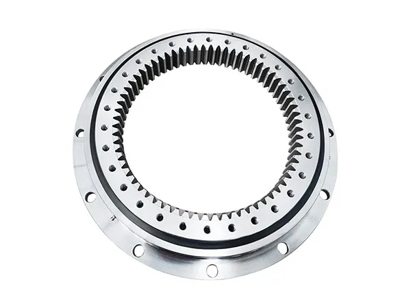
Flange bearings

4. Lubrication Procedures:

Frequency: This is highly dependent on the operating conditions and the manufacturer’s recommendations. A general guideline is:

Light Duty: Every 100-250 operating hours.

Medium Duty: Every 50-100 operating hours.

For more detailed information about flange slewing bearing lubrication, please click here: https://www.mcslewingbearings.com/a/news/flange-bearing-lubrication.html

Choosing the right material for a slewing bearing is crucial for its performance, longevity, and overall cost-effectiveness. The “best” material depends heavily on the specific application, load requirements, environmental conditions, and budget.

Slewing Bearing Materials

slewing bearing

Races (Rings): Typically made from hardened steel.

Carbon Steel (e.g., 1045, 1050): Most common and economical choice for light to medium-duty applications.

Alloy Steel (e.g., 4140, 4340, 50CrMo4, 42CrMo4): Offers higher strength, toughness, wear resistance, and hardenability. Used for medium to heavy-duty applications.

Stainless Steel (e.g., 304, 316, 440C): Used in corrosive environments or where hygiene is critical (food processing, marine applications, medical equipment). 440C is often used for races that require hardening.

Rolling Elements (Balls or Rollers): Usually made from high-carbon chromium bearing steel.

High-Carbon Chromium Bearing Steel (e.g., 52100, 100Cr6): The industry standard for rolling elements due to its exceptional hardness, wear resistance, and ability to withstand high contact stresses.

Ceramic (e.g., Silicon Nitride – Si3N4): Used in specialized applications where extremely high speeds, high temperatures, or non-magnetic properties are required.

Stainless Steel (e.g., 440C): Used in corrosive environments for rolling elements.

Cage/Separator: Keeps rolling elements separated and evenly spaced. Materials vary depending on the application.

Steel (e.g., Low-Carbon Steel, Stainless Steel): Common for general-purpose applications.

Brass/Bronze: Offers good wear resistance and damping properties.

Polyamide/Nylon (Plastic): Lightweight and quiet, suitable for lower-speed applications.

Factors to Consider When Choosing Materials

slewing bearing

Load Requirements:

Static Load: The maximum load the bearing must withstand when stationary. Higher loads require stronger materials like alloy steels.

Dynamic Load: The load the bearing must withstand while rotating. This affects fatigue life, so materials with higher fatigue strength (e.g., alloy steels, high-carbon chromium steel for rolling elements) are needed.

Impact Load: Sudden, high-energy loads. Require materials with high toughness and impact resistance (e.g., certain alloy steels).

For more detailed information on slewing bearing material comparison, please click here: https://www.mcslewingbearings.com/a/news/slewing-bearing-material-comparison.html

Crossed roller bearings are precision bearings used in applications requiring high stiffness, rotational accuracy, and load-bearing capacity. Proper installation is crucial to ensure smooth operation and longevity.Installing cross roller bearings correctly is crucial for their performance and longevity.

Crossed Roller Bearing Installation

cross roller bearings

I. Preparation is Key

Cleanliness: This is paramount. Cross roller bearings are highly sensitive to contamination.

Work Area: Clean your workbench or work area thoroughly. Use a lint-free cloth and a suitable solvent to remove any grease, dirt, or debris.

Bearing: Inspect the bearing out of its packaging. Look for any signs of damage (dents, scratches, rust) on the rollers, races, and cage. Clean the bearing if necessary, but be very gentle. Avoid harsh solvents that might damage the lubricant. Many bearings come pre-lubricated and sealed; excessive cleaning could remove the essential lubrication. If cleaning is necessary, use a solvent compatible with the existing lubricant and re-lubricate with a high-quality grease that meets the bearing’s specifications.

Housing and Shaft (or Mating Components): Thoroughly clean the housing bore (where the outer ring will sit) and the shaft (or mounting surface where the inner ring will sit). Remove any burrs, dings, or paint. Use a bore gauge and micrometer to verify that the dimensions are within the specified tolerances for the bearing’s installation.

Inspection:

Bearing: Visually inspect the bearing for any damage incurred during shipping. Rotate the rings gently to feel for any roughness or binding.

Housing and Shaft/Mating Parts: Check for proper dimensions and roundness. Out-of-round or undersized/oversized components can cause preload issues, premature wear, and reduced bearing life. Refer to the bearing manufacturer’s specifications for recommended fits and tolerances.

Confirm Bearing Type: Understand whether you are installing a split inner ring, split outer ring, or an integrated bearing. Each type requires a slightly different installation approach.

Tools:

Bearing Heater (Optional but Recommended for Larger Bearings): Heating the bearing to expand it slightly makes installation much easier and reduces the risk of damage. Use a controlled bearing heater, never an open flame.

Installation Tool/Press: A bearing press or a properly sized installation sleeve is crucial for applying even pressure during installation. Avoid hammering directly on the bearing rings.

Torque Wrench: Use a calibrated torque wrench to tighten the mounting bolts to the specified torque.

Dial Indicator/Gauge: For checking runout and alignment after installation.

For more detailed information on the correct installation method of cross roller bearings, please click here: https://www.mcslewingbearings.com/a/news/crossed-roller-bearing-installation.html

Tempered glass is a type of safety glass that has been tempered in a glass tempering furnace to increase its strength and impact resistance. This process involves heating the glass to a high temperature (usually around 600-700°C) and then rapidly cooling it through a quenching process. However, in some cases, tempered glass may crack or even break unexpectedly after quenching. If tempered glass breaks after quenching, especially if it happens repeatedly, it indicates a problem with your tempering process.

Causes and solutions for cracking of tempered glass after quenching

glass tempering furnace

1. Temperature Problems:

Too High Quenching Temperature: If the glass is too hot before quenching, the rapid cooling can create excessive stress that exceeds the glass’s ability to withstand it, leading to breakage. The ideal temperature is slightly below the softening point of the glass.

Uneven Heating: If the glass isn’t heated uniformly, some areas will be hotter than others. The cooler areas might not develop sufficient stress during quenching, while the hotter areas are overstressed. This differential stress can cause fracture.

Incorrect Temperature Measurement: Faulty thermocouples or improper calibration of the temperature monitoring system can lead to inaccurate temperature readings, resulting in incorrect quenching temperatures.

2. Quenching Issues:

Quenching Rate Too Rapid: If the cooling is too fast, the surface cools and contracts much faster than the inner layers, creating extreme stress. Adjust the air pressure, nozzle configuration, or quenching time to achieve a more controlled cooling rate.

Uneven Quenching: Similar to uneven heating, uneven cooling leads to differential stress. This could be caused by:

Clogged Air Nozzles: Obstructed nozzles in the quenching system result in inconsistent airflow across the glass surface.

Uneven Air Pressure: Fluctuations in air pressure during the quenching cycle can cause variations in cooling rates.

Poor Nozzle Design: Inadequate nozzle design can lead to uneven air distribution.

Improper Glass Placement: The glass needs to be positioned correctly within the quenching zone to ensure uniform airflow around its surfaces.

3. Glass Quality and Preparation:

Surface Defects: Scratches, chips, or other surface imperfections act as stress concentrators. Even minor flaws can become points of fracture during the tempering process. Thoroughly inspect the glass before tempering and discard any pieces with noticeable defects.

Edge Damage: Damaged edges are particularly vulnerable. Ensure the edges are smooth and free of chips or cracks. Edge grinding or seaming can help minimize stress concentration.

For more detailed information on why my tempered glass cracks after quenching, please visit: https://www.shencglass.com/en/a/news/tempered-glass-cracked-after-quenching.html

Optimizing glass product quality through a glass tempering furnace requires precise control over multiple factors, including temperature, heating time, cooling rate, and glass handling.Optimizing glass product quality through a glass tempering furnace is a complex process that involves careful control and monitoring of several factors.

glass tempering furnace

1. Pre-Tempering Processes (Before the Furnace):

Glass Selection & Quality:

Raw Material Quality: Start with high-quality glass sheets free of inclusions, bubbles, or surface defects.

Glass Thickness & Type: Ensure the glass type (e.g., float glass, low-E glass) is suitable for tempering and that the thickness is within the furnace’s capabilities. Incorrect thickness can lead to uneven heating and tempering.

Cleanliness: Thoroughly clean the glass before it enters the furnace. Contaminants like dust, oil, or fingerprints can cause uneven heating, spotting, or adhesion issues. Use appropriate glass cleaners and deionized water for rinsing.

Cutting & Edge Work:

Accurate Cutting: Precise cutting is crucial for uniform heating and stress distribution. Use automated cutting tables and laser alignment systems for optimal accuracy.

Edge Processing: Smooth, polished, and defect-free edges are critical. Chips, cracks, or sharp edges can act as stress concentrators, leading to breakage during or after tempering. Use grinding, polishing, or seaming machines to achieve high-quality edges.

Hole Drilling/Notching (if applicable): Carefully drill or notch holes before tempering. Sharp corners or imperfections around holes are significant stress points. Use CNC machining with precise settings.

Low-E Coating Consideration:

Coating Compatibility: Ensure the low-E coating is compatible with the tempering process. Some coatings may require specific temperature profiles or protective measures.

For more detailed information on how to optimize glass product quality through glass tempering furnaces, please visit: https://www.shencglass.com/en/a/news/optimization-of-glass-product-quality.html

The price of a glass tempering furnace can vary dramatically depending on a number of factors. It’s a significant investment, and understanding the price range and the variables impacting it is crucial.

Glass Tempering Furnace Price

glass tempering furnace

Small, batch-type furnaces (for small-scale production or labs): Can range from $50,000 to $200,000 USD. These are generally for smaller glass sizes and lower production volumes.

Medium-sized, continuous furnaces: Typically range from $200,000 to $800,000 USD. These offer higher throughput and are suitable for medium-sized glass fabrication shops.

Large, high-capacity continuous furnaces (for industrial production): Can range from 800,000 to several million USD(1,000,000 – $5,000,000+). These are designed for high-volume, 24/7 operation and larger glass sizes.

Key Factors Affecting the Price

glass tempering furnace

Size and Capacity:

Glass Size: The maximum dimensions of the glass that the furnace can temper are a primary price driver. Larger glass requires a larger furnace, more heating elements, and a more robust cooling system.

Production Volume/Throughput: How many sheets of glass can the furnace temper per hour or per day? Higher capacity furnaces are more expensive. Continuous furnaces generally have higher throughput than batch-type furnaces.

Type of Furnace:

Batch vs. Continuous: Batch furnaces temper glass in discrete batches, while continuous furnaces have glass continuously moving through the heating and cooling zones. Continuous furnaces are more expensive but offer higher productivity.

Horizontal vs. Vertical: Horizontal furnaces are more common and versatile. Vertical furnaces are often used for specific applications (like tempering very long glass panels) and can have specialized price implications.

For more detailed information on factors affecting the price of glass tempering furnaces, please click here: https://www.shencglass.com/en/a/news/factors-affecting-the-price-of-glass-tempering-furnace.html

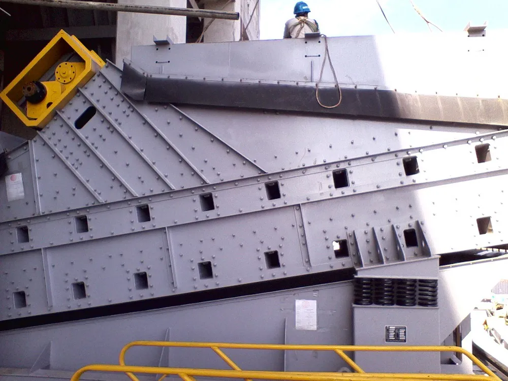
Vibrating screens are essential in industries such as mining, aggregate processing, and material handling, where they are used for sorting and classifying materials. However, their operation often generates significant noise, which can impact workplace safety, operator comfort, and regulatory compliance.

Excessive noise in vibrating screens is typically caused by factors such as unbalanced forces, loose components, inefficient damping, and resonance effects. Prolonged exposure to high noise levels can lead to hearing damage and reduced efficiency in industrial environments.Reducing noise in vibrating screen operation is crucial for a safer and more comfortable working environment.

How to reduce noise in vibrating screen operation

Vibrating screens

1. Identify the Source of Noise:

Impact Noise:

Material Impact: The primary source, caused by materials hitting the screen deck, screen mesh, and frame. Larger materials and higher feed rates increase impact noise.

Mechanical Impact: From the vibrating mechanism itself, worn parts, or loose connections.

Structural Noise:

Resonance: The screen frame vibrating at its natural frequency, amplifying the noise.

Transmission: Noise transmitted through the supporting structure to the surrounding environment.

Airborne Noise:

Screen Mesh Vibration: The mesh itself can vibrate and generate noise.

Aerodynamic Noise: Air movement caused by the vibrating screen.

2. Noise Reduction Strategies (Categorized):

Vibrating screens

A. Material Related Mitigation:

Feed Rate Optimization:

Reduce Feed Rate: The most straightforward solution. Optimizing the feed rate minimizes the amount of material impacting the screen surface at any given time.

Consistent Feed: Ensure a consistent, even feed to avoid surges that cause excessive impact noise.

For more detailed information on how to reduce noise during vibrating screen operation, please click here: https://www.zexciter.com/en/a/news/how-to-reduce-noise-in-vibrating-screen-operation.html

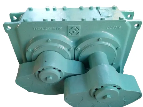
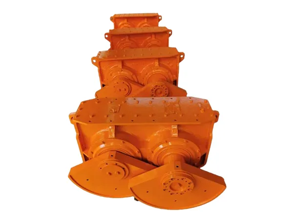
The vibrating screen exciter plays a crucial role in determining the screening efficiency, as it directly influences the vibration characteristics of the screen. The exciter is arguably the most crucial component of a vibrating screen regarding its impact on screening efficiency.

Impact of vibrating screen exciter on screening efficiency

vibrating screen exciter

Generating the Vibration: The exciter creates the vibratory motion that causes material to stratify and pass through the screen mesh. Without a properly functioning exciter, there’s no screening.

Amplitude and Frequency: The exciter controls the amplitude (the distance of the screen’s movement) and frequency (the number of oscillations per unit time) of the vibration. These two parameters are directly related to screening efficiency:

Amplitude:

Low Amplitude: Insufficient stratification of the material bed. Particles are less likely to encounter and pass through the appropriate screen openings. Can lead to blinding (screen blockage).

High Amplitude: Excessive bouncing and “dancing” of the material bed. While it might seem like aggressive screening, it can actually reduce the probability of particles passing through the screen, especially finer materials. Also increases wear and tear on the screen.

Frequency:

Low Frequency: Slower material travel across the screen, potentially leading to overloading and reduced throughput. May be ineffective for finer materials.

High Frequency: Faster material travel, potentially reducing the residence time of particles on the screen and decreasing the chance of successful separation. Can also create higher noise levels.

vibrating screen exciter

The Optimal Combination: The ideal amplitude and frequency are highly dependent on:

* Material Properties: Particle size distribution, shape, density, moisture content, stickiness, etc.

* Screen Mesh Size: Finer meshes generally require higher frequencies and lower amplitudes.

* Screen Angle: Steeper angles may require higher amplitudes to overcome gravity.

* Desired Separation Efficiency: How accurately you need to separate the different size fractions.

* Feed Rate: The amount of material being fed onto the screen.

Stroke Direction and Angle: Some exciters allow control over the stroke direction (the angle of the vibratory motion relative to the screen surface). This influences:

Material Conveyance Rate: The speed at which material moves across the screen.

For more detailed information on the effect of vibrating screen exciters on screening efficiency, please visit: https://www.zexciter.com/en/a/news/impact-of-vibrating-screen-exciter-on-screening-efficiency.html

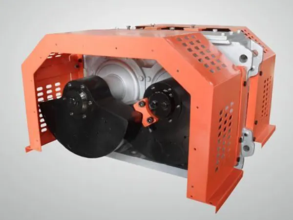
The vibrating screen exciter is a crucial component in vibrating screens, responsible for generating the necessary vibration to separate materials. The working principle of the exciter is based on unbalanced forces created by rotating masses. The working principle of a vibrating screen exciter revolves around converting rotational motion into vibratory motion. This vibratory motion is then transmitted to the screen deck, causing the material on the screen to stratify and separate based on size.

Vibrating Screen Exciter Working Principle

vibrating screen exciter

Core Components

Eccentric Weights (Unbalanced Masses): These are the key elements. An exciter typically contains one or more pairs of eccentric weights attached to a rotating shaft. “Eccentric” means the center of mass of the weight is not aligned with the axis of rotation.

Shaft: A rotating shaft, usually driven by an electric motor through a belt or direct coupling.

Bearings: Support the rotating shaft and allow for smooth, low-friction operation.

Housing/Frame: Encases and protects the internal components and provides mounting points to the vibrating screen.

Lubrication System: Essential for maintaining bearing life and reducing friction. This can be grease-based or oil-based.

The Process

Rotation: The electric motor drives the shaft to rotate.

Centrifugal Force Generation: As the eccentric weights rotate, they generate centrifugal force. The magnitude of this force is proportional to the mass of the eccentric weight, the square of the rotational speed, and the distance of the weight’s center of mass from the axis of rotation. The formula is: F = m * r * ω² where:

F = Centrifugal Force

m = Mass of the eccentric weight

r = Distance from the center of mass of the eccentric weight to the axis of rotation (the eccentricity)

ω = Angular velocity (rotational speed in radians per second)

Vibration Direction & Amplitude Control:

Angle of Eccentric Weights: The position of the eccentric weights relative to each other is crucial. By adjusting the angle between the weights, you can control the direction and type of vibration.

Circular Motion: If two eccentric weights are positioned opposite each other on the shaft, the centrifugal forces combine to create a circular or near-circular motion.

This is common in circular motion vibrating screens.

Linear Motion: If the eccentric weights are synchronized (aligned or close to aligned), the centrifugal forces mainly combine to produce linear vibration. This is seen in linear motion vibrating screens. The angle also impacts the vibration direction.

Magnitude of Eccentric Weights & Speed: The size of the eccentric weights and the speed of rotation directly impact the amplitude (the size of the vibration). Larger weights or higher speeds create larger vibrations.

Force Transmission: The vibratory force generated by the rotating eccentric weights is transmitted through the exciter’s housing to the screen deck. The exciter is rigidly connected to the screen frame to ensure efficient transfer.

For more detailed information about the working principle of the vibrating screen exciter, please click here: https://www.zexciter.com/en/a/news/vibrating-screen-exciter-working-principle.html

welding positioner significantly improves welding efficiency, quality, and safety by rotating and tilting workpieces into optimal positions for the welder. Choosing the right one requires careful consideration of your specific needs and projects.

How to Choose a Welding Positioner

welding positioner

1. Load Capacity:

What it is: This is the maximum weight the positioner can safely and effectively handle while rotating and tilting. It’s arguably the most critical factor.

How to determine your need:

Weigh your heaviest workpiece: Use a scale or consult design specifications.

Factor in fixturing: Include the weight of any jigs, clamps, or tooling used to secure the workpiece to the positioner.

Add a safety margin (essential!): Overestimate your weight requirement by at least 20-30%. This accounts for potential inaccuracies, future heavier projects, and extended equipment life. It’s better to have too much capacity than not enough.

Consequences of underestimating:

Damage to the positioner: Premature wear and tear on motors, gears, and bearings.

Unstable operation: Jerky movements, difficulty maintaining position, and potential tipping.

Safety hazard: Risk of workpiece falling or causing injury.

Types of Load Capacities: Positioners have two common load capacity ratings:

Horizontal Load Capacity: The maximum weight that can be supported when the table is in a horizontal position (0 degrees tilt). This is usually the highest load capacity.

Vertical Load Capacity: The maximum weight that can be supported when the table is in a vertical position (90 degrees tilt). This is usually less than the horizontal load capacity because the cantilevered load puts more stress on the system.

Key takeaway: Calculate the total weight accurately and always add a safety margin to ensure safe and reliable operation.

2. RPM (Rotation Speed):

What it is: This refers to the rotational speed of the positioner’s table, measured in revolutions per minute (RPM).

How to determine your need:

Welding process: Different welding processes require different speeds. For example:

GTAW (TIG) & GMAW (MIG) on thin materials: Often require higher RPMs for faster, more consistent welds.

SMAW (Stick) & SAW (Submerged Arc Welding) on thick materials: Typically need lower RPMs for slower, controlled deposition.

Workpiece diameter: Smaller diameter workpieces need higher RPMs to achieve the desired surface speed for welding. Larger workpieces need lower RPMs.

Desired travel speed: Think about how fast you want the weld bead to move. RPM is directly related to travel speed. A slower RPM will result in a slower travel speed. A faster RPM will result in a faster travel speed.

Operator skill: Experienced welders might prefer faster rotation speeds, while beginners may benefit from slower, more controlled movements.

Adjustable RPM is crucial: Look for positioners with a variable speed control to fine-tune the rotation based on the specific application. Consider a wide RPM range for maximum versatility.

Key takeaway: Consider your welding process, workpiece size, and desired travel speed to determine the appropriate RPM range for your positioner. Variable speed control is highly recommended.

welding positioner

3. Tilt Angle:

What it is: This refers to the range of angular movement that the positioner’s table can achieve. It’s measured in degrees from horizontal (0°) to vertical (90°) or beyond.

How to determine your need:

Workpiece geometry: Complex shapes and multi-faceted assemblies often require a wider tilt angle range to access all weld joints comfortably.

Welding position requirements: Some welding codes or specifications may dictate specific welding positions (flat, horizontal, vertical, overhead). The tilt angle must be sufficient to achieve these positions.

For more detailed information on welding positioner selection, please click here: https://www.bota-weld.com/en/a/news/load-capacity-rpm-and-tilt-angle.html